Digital Cinema Initiatives, LLC (DCI) is the author and creator of this specification
for the purpose of copyright and other laws in all countries throughout the world.
The DCI copyright notice must be included in all reproductions, whether in whole or
in part, and may not be deleted or attributed to others. DCI hereby grants to its
members and their suppliers a limited license to reproduce this specification for
their own use, provided it is not sold. Others should obtain permission to reproduce
this specification from Digital Cinema Initiatives, LLC.
This document is a specification developed and adopted by Digital Cinema Initiatives,
LLC. This document may be revised by DCI. It is intended solely as a guide for companies
interested in developing products, which can be compatible with other products, developed
using this document. Each DCI member company shall decide independently the extent
to which it will utilize, or require adherence to, these specifications. DCI shall
not be liable for any exemplary, incidental, proximate or consequential damages or
expenses arising from the use of this document. This document defines only one approach
to compatibility, and other approaches may be available to the industry.
This document is an authorized and approved publication of DCI. Only DCI has the right
and authority to revise or change the material contained in this document, and any
revisions by any party other than DCI are unauthorized and prohibited.
Compliance with this document may require use of one or more features covered by proprietary
rights (such as features which are the subject of a patent, patent application, copyright,
mask work right or trade secret right). By publication of this document, no position
is taken by DCI with respect to the validity or infringement of any patent or other
proprietary right. DCI hereby expressly disclaims any liability for infringement of
intellectual property rights of others by virtue of the use of this document. DCI
has not and does not investigate any notices or allegations of infringement prompted
by publication of any DCI document, nor does DCI undertake a duty to advise users
or potential users of DCI documents of such notices or allegations. DCI hereby expressly
advises all users or potential users of this document to investigate and analyze any
potential infringement situation, seek the advice of intellectual property counsel,
and, if indicated, obtain a license under any applicable intellectual property right
or take the necessary steps to avoid infringement of any intellectual property right.
DCI expressly disclaims any intent to promote infringement of any intellectual property
right by virtue of the evolution, adoption, or publication of this document.
A number of significant technology developments have occurred in the past few years
that have enabled the digital playback and display of feature films at a level of
quality commensurate with that of 35mm film release prints. These technology developments
include the introduction of: high-resolution film scanners, digital image compression,
high-speed data networking and storage, and advanced digital projection. The combination
of these digital technologies has allowed many impressive demonstrations of what is
now called “Digital Cinema.” These demonstrations, however, have not incorporated all
of the components necessary for a broad-based commercially viable Digital Cinema system.
These demonstrations have created a great deal of discussion and confusion around
defining the quality levels, system specifications, and the engineering standards
necessary for implementing a comprehensive Digital Cinema system.
Digital Cinema Initiatives, LLC (DCI) is the entity created by seven motion picture
studios: Disney, Fox, Metro-Goldwyn-Mayer[1], Paramount Pictures, Sony Pictures Entertainment,
Universal Studios, and Warner
Bros. Studios. The primary purpose of DCI is to establish uniform specifications for
Digital Cinema. These DCI member companies believe that the introduction of Digital
Cinema has the potential for providing real benefits to theater audiences, theater
owners, filmmakers and distributors. DCI was created with recognition that these benefits
could not be fully realized without industry-wide specifications. All parties involved
in the practice of Digital Cinema must be confident that their products and services
are interoperable and compatible with the products and services of all industry participants.
The DCI member companies further believe that Digital Cinema exhibition will significantly
improve the movie-going experience for the public.
The document defines technical specifications and requirements for the mastering of,
distribution of, and theatrical playback of Digital Cinema content. The details are
in the following sections:
Digital Cinema Distribution Master (DCDM): This section provides specifications for
the image, audio, subtitle (Timed Text and
subpictures) Digital Cinema Distribution Masters. The DCDM-Image defines a common
set of image structures for Digital Cinema by specifying an image containers and colorimetry
for a Digital Cinema Distribution Master (DCDM). The DCDM-Audio specifies the following
characteristics: bit depth, sample rate, minimum channel count, channel mapping and
reference levels. The DCDM-subtitles specifies the format of a Digital Cinema subtitle
track file. A subtitle track file contains a set of instructions for placing rendered
text or graphical overlays at precise locations on distinct groups of motion picture
frames. A subtitle track file is an integral component of a Digital Cinema composition
and may be present in both mastering and distribution file sets.
Compression (Image): Specifies the DCI compliant JPEG 2000 codestream and JPEG 2000
decoder.
Packaging: This section defines the requirements for packaging the DCDM (image, audio
and subtitle)
files using (where possible) existing Material eXchange Format (MXF) specifications
and eXtensible Mark up Language (XML). The output of this process is the Digital Cinema
Package (DCP). This section also defines the requirements for encrypting the essence
(sound, picture
and subtitles) of the DCP.
Transport: Defines the movement from distribution centers to theater locations using
physical
media, virtual private networks or satellite communications.
Theater Systems: Provides requirements for all equipment necessary for theatrical
presentation in
a typical theater environment. This encompasses digital projectors, media blocks,
storage systems, sound systems, the DCP files ingest, theater automation, Screen Management
System (SMS) and Theater Management Systems (TMS).
Projection: This section defines the projector and its controlled environment, along
with the
acceptable tolerances around critical image parameters for Mastering and general Exhibition
applications. The goal is to provide a means for achieving consistent and repeatable
color image quality. Two levels of tolerances are specified: a tighter tolerance for
mastering rooms where critical color judgments are made, and a wider tolerance for
satisfactory reproduction in general public exhibition.
Security: The security chapter provides requirements and fundamental specifications
for persistent
content protection and controlled access in an open security architecture. These objectives
are achieved with high security in a multi-user environment via the application of
well respected security and encryption standards in primarily three areas: 1) content
encryption, 2) security (key) management and 3) high integrity event logging and reporting.
This document consists of normative text and, optional informative text. Normative
text is text that describes the elements of the design that are indispensable or contains
the conformance language keywords: “shall”, “should” or “may”. Informative text is
text that is potentially helpful to the user, but not indispensable and can be removed,
changed or added editorially without affecting interoperability. Informative text
does not contain any conformance keywords. All text in the document is, by default,
normative except: any section titled “Introduction”, any section explicitly labeled
as “Informative”, or individual paragraphs that start with the word “Note.” Normative
references are those external documents referenced in normative text and are indispensable
to the user. Informative, or bibliographic, references are those references made from
informative text or are otherwise not indispensable to the user.
The keywords “shall” and “shall not” indicate requirements that must be strictly followed
in order to conform to the document and from which no deviation is permitted.
The keywords “should” and “should not” indicate that among several possibilities one
is recommended as particularly suitable, without mentioning or excluding others; or
that a certain course of action is preferred but not necessarily required. In the
negative form, a certain possibility or course of action is deprecated but not prohibited.
The keywords “may” and “need not” indicate a course of action permissible within the
limits of the document.
The keyword “reserved” indicates that a condition is not defined and shall have no
meaning. However, it may be defined in the future. The keyword “forbidden” is the same as reserved,
except that the condition shall never
be defined in the future.
A compliant implementation is one that includes all mandatory provisions (“shall”)
and, if implemented, all recommended provisions (“should”) as described. A compliant
implementation need not implement optional provisions (“may”).
Requirements are indicated with the key phrases “is required to”, “is encouraged to”
and “can” which represent “shall,” “should” and “may” (had the text been in a separate
requirements document). This is necessary in order to distinguish requirements from
the specification conformance language.
Sentences with the following keywords are italics: shall, shall not, should not, is required, is
not required, is not encouraged and is encouraged.
The names of standards publications and protocols are placed in [bracketed text].
International and industry standards contain provisions, which, through reference
in this text, constitute provisions of this specification. The most recent editions of the referenced standards
shall be valid unless otherwise
exempted in this specification. These referenced standards are subject to revision, and parties to
agreements based
upon this specification are encouraged to investigate the possibility of applying
the most recent editions of the referenced standards. Section 10. is a glossary of
technical terms and acronyms used throughout this specification.
The reader is encouraged to refer to the glossary for any unfamiliar terms and acronyms.
Trademarked names are the property of their respective owners.
Portions of SMPTE standards are incomplete with respect to many behavior requirements,
the subjects of which are typically addressed by SMPTE as "Informative"
text and informative "Notes." Sections of this DCI Specification identify normative requirements that shall
take
precedence over such SMPTE "Informative" text and informative "Notes."
At the onset of writing a specification for a Digital Cinema system, DCI acknowledged
certain fundamental requirements, which are:
The Digital Cinema system shall have the capability to present a theatrical experience
that is better than what one could achieve now with a traditional 35mm Answer Print.
This system should be based around global standards, or DCI specifications, that are
embraced around the world so that content can be distributed and played anywhere in
the world as can be done today with a 35mm film print. These standards should be open
published industry standards that are widely accepted and codified by national and
international standards bodies such as: ANSI, SMPTE, and ISO/IEC. To the extent that
it is possible, the Digital Cinema system shall emulate theater operations and the
theater business model, as it exists today.
The system specification, global standards and formats should be chosen so that the
capital equipment and operational costs are reasonable and exploit, as much as possible,
the economies of scale associated with equipment and technology in use in other industries.
The hardware and software used in the system should be easily upgraded as advances
in technology are made. Upgrades to the format shall be designed in a way so that
content may be distributed and compatibly played on both the latest DCI-compliant
hardware and software, as well as earlier adopted DCI-compliant equipment installations.
The Digital Cinema system shall provide a reasonable path for upgrading to future
technologies. It shall be based upon a component architecture (e.g., Mastering, Compression,
Encryption, Transport, Storage, Playback, Projection) that allows for the components
to be replaced or upgraded in the future without the replacement of the complete system.
It is the intention of this Digital Cinema specification to allow for advances in
technology and the economics of technology advancement. It has been recognized that
these advances may most likely affect the mastering and projection of Digital Cinema
content. Therefore, this document will specify, for example, a resolution and color
space that may not be obtained in a present day mastering or projection system. However,
it is the intent that the rest of the Digital Cinema system be capable of transporting
and processing up to the technical limits of the specification.
This document specifies a baseline for the implementation of a Digital Cinema system.
The goal of backwards compatibility in this context is to allow, for example, new
content at higher resolution and color space to be played out on a projection system
that meets the baseline implementation.
The Digital Cinema system shall also not preclude the capability for alternative content
presentations.
The Digital Cinema system shall provide a reliability and availability that is equal
to, or better than, current film presentation.
Protection of intellectual property is a critical aspect of the design of the system.
This security system should be designed using a single common encryption format along
with keys to decrypt the content. The method should provide a means to keep the content
encrypted from the time it is encoded in post-production until it is projected on
a theater screen. Only trusted entities, deployed in secure environments or implementing
physical protection, will be given access to the decrypted content. Content will be
decrypted contingent upon usage rules agreed on by content owners, Distributors and
Exhibitors. The system should also be renewable in case of a breach of security in
any part of the system, and include forensic Marking of the content for providing
traceable forensic evidence in the case of a theft of the content.
For the purpose of documenting the specific requirements and specifications for a
Digital Cinema system, it is helpful to divide the system into a set of components[2] ,
which are:
Digital Cinema Distribution Master (DCDM) – Contains system requirements regarding
the uncompressed, unencrypted file or set of files containing the content and its
associated data.
Compression – Contains system requirements regarding the process that reduces redundancy
in source essence data and its inverse, decompression,
Packaging – Contains system requirements for the process of encryption and decryption
of compressed image and audio essence, wrapping and unwrapping of compressed and encrypted
files for distribution and playback.
Transport – Contains requirements related to the distribution of the packaged media.
Theater System – Contains system requirements for the equipment installed at a theater
for control, scheduling, logging and diagnostics.
Projection – Contains system requirements regarding the performance characteristics
used to display the image on the screen.
Security – Contains system requirements that bear on the protection of content intellectual
property rights. Processes for key management, link encryption, Forensic Marking and
logging are constituent elements of the security design.
The Digital Source Master (DSM) is created in post-production and can be used to convert
into a Digital Cinema Distribution Master (DCDM). The DSM can also be used to convert
to a film duplication master, a home video master, and/or a master for archival purposes.
It is not the intention of this document to, in any way, specify the DSM. This is
left to the discretion of the content provider. The content could come from a wide
range of sources with a wide range of technical levels.
When discussing Digital Cinema content, it was realized that other content besides
feature films would make use of the same digital system. Therefore, a new term was
created to refer to any content that would have similar requirements to feature film
content. The term “Composition” refers to all of the essence and metadata required
for a single presentation of a feature, or a trailer, or an advertisement, or a logo
to create a presentation using a digital system. This term will be used throughout
this document and is intended to refer to a single element such as one and only one
feature, trailer, advertisement or logo.
2.1.1.3. Digital Cinema Distribution Master (DCDM) 🔗
This document specifies a DCDM for the purpose of exchanging the image, audio and
subtitles to encoding systems and to the Digital Cinema playback system. The DCDM
is the output of the Digital Cinema post-production process (not to be confused with
the feature post-production process, which creates the DSM) and is the image structure,
audio structure, subtitle structure. These structures are mapped into data file formats
that make up the DCDM. This master set of files can then be given a quality control
check to verify items like synchronization and that the composition is complete. This
requires the DCDM files to be played back directly to the final devices (e.g., projector
and sound system) in their native decrypted, uncompressed, unpackaged form.
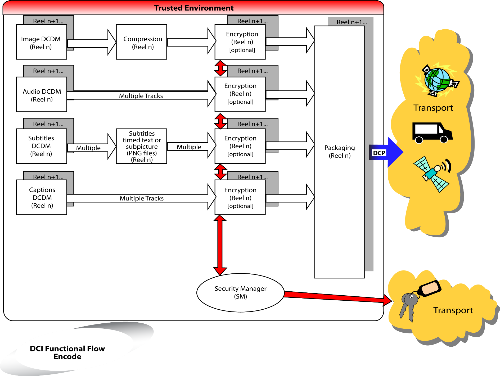
Once the DCDM is compressed, encrypted and packaged for distribution, it is considered
to be the Digital Cinema Package or DCP. This term is used to distinguish the package
from the raw collection of files known as the DCDM. Shown below is a typical flow
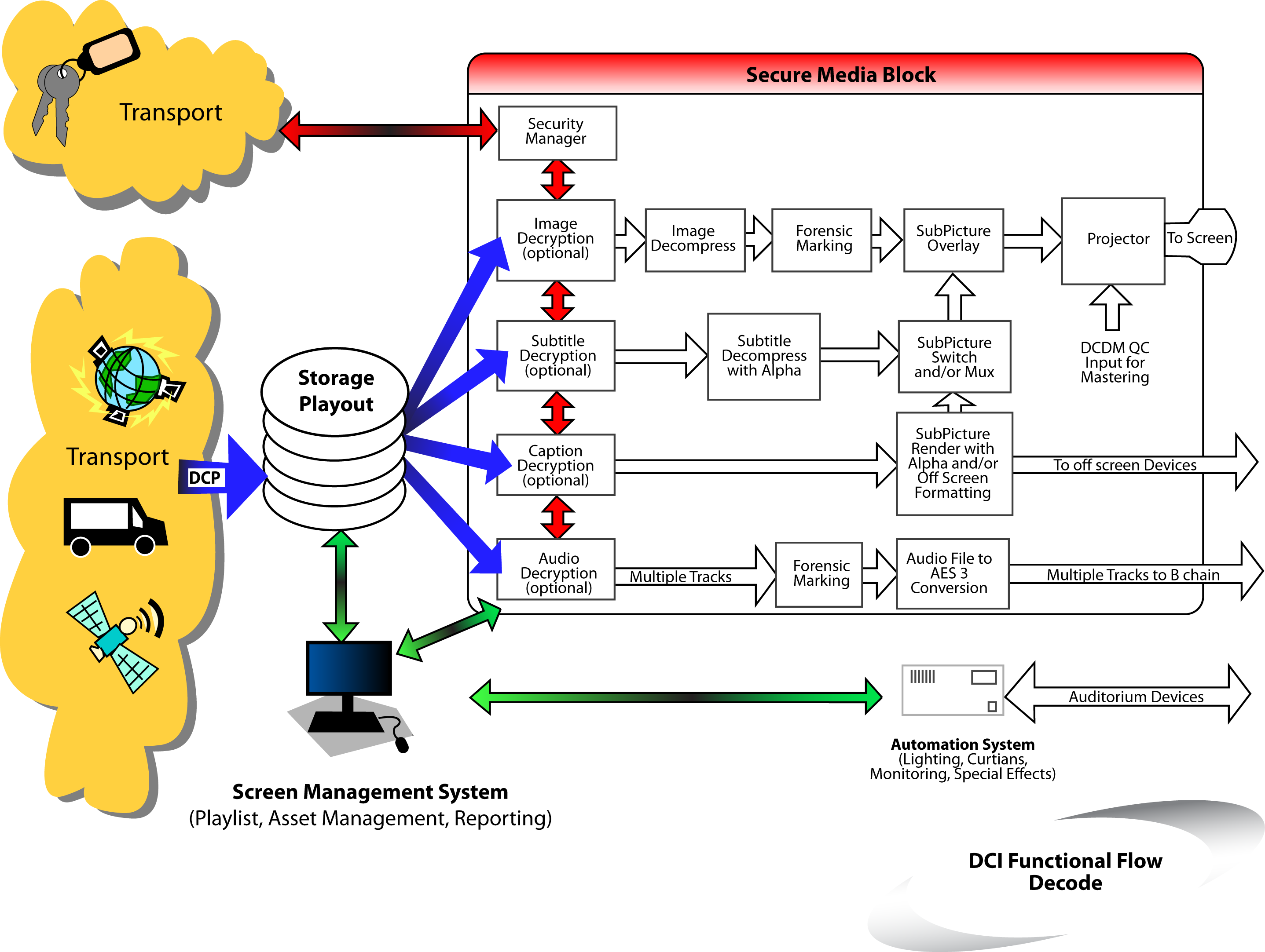
for Digital Cinema. When the DCP arrives at the theater, it is eventually unpackaged,
decrypted and decompressed to create the DCDM*, where DCDM* image is visually indistinguishable
from the original DCDM image.
DSM → DCDM → DCP → DCDM* → Image and Sound
Note: Integrated projector and Media Blocks are strongly recommended. However in the
exclusive case to accommodate a 2K, 48 FPS, 12 bit DCDM to use [SMPTE 372M Dual Link
HD-SDI] as an interface, it is acceptable, but not recommended, to allow 10 bit color
sub-sampling to create the DCDM* at the output of the Image Media Block decoder. This
bit depth reduction and color subsampling is only allowed in the single combination
of a DCDM at 2K, 48 FPS being transported over a link encrypted SMPTE 372M connection.
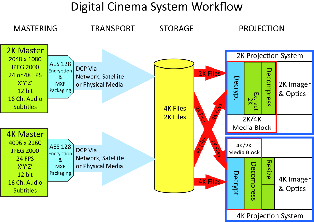
The DCDM shall use a hierarchical image structure that supports both 2K and 4K resolution
files (See Section 3.2.1. Image Concepts and Requirements) so that studios can choose to deliver either
2K or 4K masters and both 2K and 4K
projectors can be deployed and supported. The supported mastering and projecting combinations are
illustrated in Figure 3:
Hierarchical Image Structure.
Media Blocks (MB) for 2K projectors are required to be able to extract and display
the 2K-resolution component from the 2K/4K DCP file(s). Media Blocks for 4K projectors
are required to be able to output and display the full 4K DCDM. In the case of a 2K
DCDM, the output of the Media Block is a 2K image. It is the responsibility of the
4K projectors to up-sample the image.
This Digital Cinema system is built upon a data file-based design, i.e., all of the
content is made up of data stored in files. These files are organized around the image
frames. The file is the most basic component of the system.
This Digital Cinema system uses a store-and-forward method for distribution. This
allows the files to be managed, processed and transported in non-real time. Non-real
time could be interpreted as slower than real time, or faster than real time. After
being transported to the theater, the files are stored on a file server until playback.
However, during playback and projection, the Digital Cinema content plays out in real
time.
Feature films have been sub-divided for some time into discreet temporal units for
film systems called reels. This concept and practice will continue in use for the
Digital Cinema system. In Digital Cinema, a reel represents a conceptual period of
time having a specific duration chosen by the content provider. Digital Cinema reels
can then be electronically spliced together to create a feature presentation.
For the purpose of interoperability, the hardware and software used in the Digital
Cinema system shall be easily upgraded as advances in technology are made. Upgrades
to the format shall be designed in a way so that content can be distributed and played
on the latest hardware and software, as well as earlier DCI-compliant equipment installations.
The Digital Cinema system shall provide a reasonable path for upgrading to future
technologies. It shall be based upon a component architecture (e.g., Mastering, Compression,
Encryption, Transport, Storage, Playback, Projection), that allows for the components
to be replaced or upgraded in the future without the replacement of the complete system. It is the
intention of this Digital Cinema specification to allow for advances in
technology and the economics of technology advancement.
Storage and Media Block are components of the theater playback system. Storage is
the file server that holds the packaged content for eventual playback. The Media Block
is the hardware device (or devices) that converts the packaged content into the streaming
data that ultimately turns into the pictures and sound in the theater. These two components
can be physically contained together or they can be physically separate from each
other. Media Blocks are secure entities and the specific nature of that security is
defined in Section 9. Security.
The Digital Cinema Distribution Master, or DCDM, is a collection of data file formats,
whose function is to provide an interchange standard for Digital Cinema presentations.
It is a representation of images, audio and other information, whose goal is to provide
a complete and standardized way to communicate movies (compositions) between studio,
post-production and exhibition. A specific instance of a DCDM is derived from a Digital
Source Master (DSM) that is created as a result of a post-production assembly of the
elements of a movie (composition). A DCDM can be transformed into a Digital Cinema
Package for distribution to exhibition sites (see Section 5. Packaging). Alternatively,
it can be sent directly to a playback system for quality control
tasks.
For the purpose of documenting the specific requirements and specifications for the
DCDM, it is helpful to divide the system into a set of components. The specifications
and requirements for each of these components will be described in the following sections:
Image – The image specification and file format
Audio – The audio specification and file format
Subtitles
Subpicture – The pre-rendered open text specification and file format
Timed Text – The Timed Text data specification and file format
The Digital Cinema Distribution Master (DCDM) is the fundamental interchange element
in the system. Since digital mastering technology will continue to change and develop
with time, the DCDM is designed to accommodate growth. There are several areas that
will be affected by the progression of the mastering technology, such as color space,
resolution, sampling frequencies, quantizing bit depths and interfaces.
In the process of creating feature films, a Digital Source Master, or DSM, is produced.
The DSM creates many elements (e.g., Film Distribution Masters, DCDM, Home Video Masters
and Broadcast Masters). It is not the goal of this specification to define the DSM.
Instead, it is recognized that the DSM can be made of any color space, resolution,
sampling frequency, color component bit depths and many other metrics.
If the content does not meet this DCDM specification, it is the content provider’s
responsibility to convert the DSM into the DCDM specification, defined in this section,
before it can be used in the Digital Cinema system.
A set of DCDM files (image, audio, subtitles, etc.) contains all of the content required
to provide a Digital Cinema presentation. The DCDM provides two functions, an interchange
file format, and a playback format that is directly sent from the Media Block to the
projector (this is referred to as DCDM*). For use in interchange, the encoding process
can be performed in real time or non-real time. For use in playback, the DCDM* is
logically required to playback in real time.
Metadata within the DCDM provides a method to synchronize image, audio and subtitles.
This method is used to synchronize the tracks in order to maintain frame-based lip
sync from the beginning to the end of a presentation. This is different from the requirement
to synchronize the system clocks of different pieces of equipment to run at consistent
frequencies. The first part addresses the packaging of the picture, sound and subtitles
in such a way as to establish and maintain a timing relationship between these tracks
of essence. The second part addresses the inter-operability of equipment in a theater
system and is therefore discussed in Section 7. Theater Systems.
The DCDM is required to use a common standardized file format for each element (image,
audio, subtitles, etc.). The DCDM image file format is required to be an MXF-conformant
file, based on existing SMPTE standards. The DCDM audio file format is required to
be based on Broadcast Wave.
The DCDM image structure is required to support a frame rate of 24.000 Hz. The DCDM
image structure can also support a frame rate of 48.000 Hz for 2K image content only.
The frame rate of any individual DCDM master is required to remain constant. Metadata
is carried in the image data file format to indicate the frame rate.
Files within the DCDM set are required to carry information to provide for frame-based
synchronization between each file. At a minimum, they are required to include a “start
of file” and a continuous frame count.
This section defines a common interchange for Digital Cinema uncompressed image structures
and files. This includes an image structure, aspect ratios, common color space, bit
depth, transfer function, and the file format required to present content properly
to a Digital Cinema projector.
The SMPTE published standard "SMPTE 428-1: D-Cinema Distribution Master - Image Characteristics"
shall be utilized.
The DCDM Image Structure shall be mapped into the TIFF Rev 6.0 File Format and further constrained as
follows:
16 bits each per X', Y', and Z' channel, stored in the nominal TIFF R, G and B channels.
The DCDM gamma-encoded X', Y' and Z' color channels are represented by 12-bit unsigned
integer code values. These 12 bits are placed into the most significant bits of 16-bit
words, with the remaining 4 bits filled with zeroes.
The image orientation shall place the first pixel in the upper left corner of the
image.
The DCDM picture file shall contain only the active pixels in the image. In other
words, it is not allowed to pad the picture to the full size of the DCDM container.
The DCDM file format is required to contain metadata that allows for synchronization
of the images with other content:
Each directory shall contain only one contiguous sequence of frames.
For assembled reels, a separate directory shall be used for each reel with the following
naming convention:
CompositionName.Reel_#
For inserts, the directory naming convention shall be:
FeatureName.Reel_#.Insert_#
Each reel shall contain sequentially numbered frames, using the following file naming
convention. All names when sorted alphabetically shall be in sequential order (leading
zeroes required). Therefore, the only thing that changes in the sequence is the frame numbers.
Image information and parameters, required to successfully interchange the DCDM Image
Structure, shall be provided to the mechanism that will ingest the DCDM.
Each frame in the reel shall contain accurate and complete metadata,but it is permissible to read and
extract the reel-based metadata from the first frame
of a reel to use as a metadata “slate” for the rest of the frames in the reel.
The information, as shown in Table 4 below, is the minimum required information to
successfully interchange files.
Channel labeling indicates where an audio channel is to be reproduced in an auditorium.
Channel routing is the process of using these labels to direct each audio channel
to the Media Block output that corresponds to the intended loudspeaker or device.
The playback device is required to perform channel routing.
The channel labels and schema in SMPTE ST 429-2 "D-Cinema Packaging-DCP Operational
Constraints" shall be utilized.
The audio file format shall comply with the Broadcast Wave file format (.wav), per
[ITU Tech 3285 version 1 (PCM WAVE coding)], is extended and constrained as further
described here.
The audio file shall remain uncompressed throughout the Digital Cinema system. This
shall include packaging, distribution and storage.
The Broadcast Wave (.wav) file is required to contain metadata that indicates the
first sample of audio data. The metadata is also required to contain a continuous
frame count relative to the image as well as the sample rate.
Object-Based Audio Essence (OBAE) implementations shall meet all requirements as defined
in the Digital Cinema Object-Based Audio Addendum approved by Digital Cinema Initiatives,
LLC (DCI) on 23 August 2018.
This specification refers to OBAE in lieu of Immersive Audio.
Digital Cinema has a subtitling system that can convey multiple languages. Along with
subtitling, there are text localizations, titling and captioning that may also be
a part of the new Digital Cinema experience. However, captioning and subtitling are
identified as two separate systems having different roles in the presentation of content
and may have different methods of rendering.
Traditionally, the audience for captioning is the deaf and hard of hearing (D/HOH).
The delivery can be done in different ways. These include closed systems that are
optional-to-the-viewer delivery and are usually displayed on a personal device (such
as a wireless receiver), or delivery to an obscured device that is viewable with an
appliance (such as a rear-wall display viewed through a mirror).
Subtitling is generally associated with a foreign language translation for localizing
a movie in a particular geographic territory. Subtitles are typically open or displayed
on the screen as part of the movie, without option. Subtitling and localizations are
generally designed for a particular look with creatively chosen fonts and drop shadows.
With captioning, the source language (what is spoken in the movie) and the target
language (what appears as captions) are most often, as in the case of English, the
same. For subtitling, the source language and target language are different because
the goal of subtitling is to translate the movie.
Subtitles and captions, if supplied, may be one or more of the following:
Pre-composited into the Digital Cinema image files (burned-in)
Pre-rendered PNG bitmaps (subpicture), or
Documents containing text and attributes for:
Rendering in a specified font (Timed Text) and overlaid by the server, an in-line
processor or the Digital Cinema projector
LED displays driven by a captioning processor receiving data from the Digital Cinema
server, or
Separate projection systems driven by a captioning processor receiving data from the
Digital Cinema server
Section 3.4.2. below defines the subpicture specifications, while
Section 3.4.3. Timed
Text Concepts and Requirements, defines the specification for Timed Text streams,
which can be used for either subtitles
or captions or both. Burned-in subtitles are not addressed since they are something
that would occur in the mastering of the content and would be inherent in the image.
A subpicture data stream is a multiple-image data stream intended for the transport
of visual data supplemental to a motion picture. The data is designed for graphic
overlay with the main image of a Digital Cinema motion picture. It is designed only
for an open display and not for a closed display. It is envisioned that the subpicture
data stream, when employed, will typically be used for the transport of subtitle data.
Subpicture data is required to be encoded as a standardized, XML-based document. Such
a standard is required to define both Timed Text and subpicture encoding methods allowing
mixed-media rendering. Subpicture frames are required to be encoded as [ISO/IEC 15948:2004]
PNG files.
The PNG file is required to be rendered with knowledge of color space and pixel matrix
of the DCDM. The PNG file is required to be mastered at the same resolution as the
DCDM.
For example, a DCP containing a 4K master will require 4K PNG files and no other resolution
PNG files. When played on a 2K projector, it is the responsibility of the 2K projection
system to downsample the 4K PNG files such that they display with the correct size
with respect to the image data. And, a DCP containing a 2K master will require 2K
PNG files and no other resolution PNG files. When played on a 4K projector, it is
the responsibility of the 4K projection system to upsample the 2K PNG files appropriately.
The XML navigation file specifies the temporal resolution of the subpicture file.
A Frame count, Time In, Time Out, Fade Up Time and Fade Down Time, which correspond
to the image, shall be included. The subpicture frame rate shall be equal to the frame
rate of the associated DCDM image file.
The equipment or system that encodes or decodes the subpicture file is required to
ensure that temporal transitions within the subpicture file are correctly synchronized
with other associated DCDM files. The Digital Cinema equipment and subpicture file
is required to re-synchronize after a restart of the system.
Font files are required to be used to render Timed Text for subtitle applications.
Font files can be used to render Timed Text for caption applications. When used, font
files are required to conform to [ISO/IEC 14496-22:2007(E) Information
technology - Coding of audio-visual objects - Part 22: Open Font Format].Timed Text files are required to be
accompanied by all font files required for reproduction
of the Timed Text.
The Timed Text file format is required to support a default character set. It is required
that there be a default Unicode™ character set and a default font for that character
set.
In event that an external font file is missing or damaged, the subtitle rendering
device is required to use a default font supplied by the manufacturer. The default
character set is required to be a Unicode™ ISO Latin-1 character set. The default font is required to
conform to [ISO/IEC 14496-22:2007(E) Information technology
- Coding of audio-visual objects - Part 22: Open Font Format] and support the ISO
Latin-1 character set.
The Timed Text format shall allow the display of multiple captions simultaneously.
There shall be a maximum number of 3 lines of text allowed for simultaneous display.
Note: This allows for spatial representation for captions when two people are talking
simultaneously.
The equipment or system that encodes or decodes the Timed Text file is required to
ensure that temporal transitions within the data stream are correctly synchronized
with other associated DCDM data streams.
Current day control systems, usually called automation systems, orchestrate theater
sub-systems such as curtains, masking and lights. Digital Cinema control methods are
expected to differ significantly from those found in theaters today. Supervisory types
of control will be much broader in application than in today’s systems, allowing interface
to specialized controls for theatrical events.
Many of today’s automation controls are driven by a time-based event list such as
the system's Show Playlist, and can be classified by their show control functions,
as in the partial list below.
First frame of content
First frame of intermission
First frame of end credits
First frame of end credits on black
Last frame of content
Show control events or cues are required for the theater system operator to pre-program
the timing of show control events. Such events or cues may indicate events such as the beginning of the
title, beginning
of the intermission, beginning of the credits, and the end of the feature. The events
or cues will normally be placed into the Digital Cinema Composition Playlist, as defined
in Section 5. Packaging.
Image Compression for Digital Cinema uses data reduction techniques to decrease the
size of the data for economical delivery and storage. The system uses perceptual coding
techniques to achieve an image compression that is visually lossless. It is important
to note that image compression is typically used to ensure meeting transmission bandwidth
or media storage limitations. This results in image quality being dependent on scene
content and delivered bit rate. Digital Cinema image compression is much less dependent
upon bandwidth or storage requirements, thereby making bit rate dependent on desired
image quality rather than the reverse.
A 2K distribution – the resolution of the DCDM*[3] container is 2048x1080.
A 4K distribution – the resolution of the DCDM*[3] container is 4096x2160.
A 2K decoder outputs up to 2048x1080 resolution data.
A 4K decoder outputs up to 4096x2160 resolution data from a 4K compressed file and
outputs up to 2048x1080 resolution data from a 2K compressed file.
All decoders shall decode both 2K and 4K distributions. It is the responsibility of the 4K projector to
upres the 2K file. In the case of
a 2K decoder and a 4K distribution, the 2K decoder need read only that data necessary
to decode a 2K output from the 4K distribution. The decoder (be it a 2K decoder or
a 4K decoder) need not up-sample a 2K image to
a 4K projector or down-sample a 4K image to a 2K projector.
Enhanced parameter choices shall not be allowed in future distribution masters, if
they break decodability in a deployed compliant decoder.
All decoders shall decode each color component at 12 bits per sample with equal color/component
bandwidth. Decoders shall not subsample chroma.
A 4K decoder shall decode all data for every frame in a 4K distribution. A decoder
shall not discard data (including resolution levels or quality layers) to keep up
with peak decoding rates.
A 2K decoder shall decode 2K data for every frame in a 4K distribution and it shall
decode a 2K distribution. It may discard only the highest resolution level of a 4K
distribution. It shall not discard other data such as further resolution levels or
quality layers.
All decoders shall implement the 9/7 inverse wavelet transform with at least 16 bit
fixed point precision.
All decoders shall implement the inverse Irreversible Color Transform (ICT) using
at least 16 bit fixed point precision.
All codestreams shall fully conform with [ISO 15444-1:2006 Amendment 1], as more fully
constrained as follows:
The capability parameter for a 2K distribution shall be Rsiz = 3, for a 4K distribution
it shall be Rsiz = 4.
All image frames shall be untiled. More precisely, the entire image shall be encoded
as a single tile.
The image and tile origins shall both be at (0, 0).
There shall be no more than 5 wavelet transform levels for 2K content and no more
than 6 wavelet transform levels for 4K content. There shall be no less than one wavelet
transform level for 4K content. Additionally, every color component of every frame
of a distribution shall have the same number of wavelet transform levels.
Codeblocks shall be of size 32x32.
The codeblock coding style shall be SPcod, SPcoc = 0b00000000.
All precinct sizes at all resolutions shall be 256x256, except the lowest frequency
subband, which shall have a precinct size of 128x128.
There shall be no region of interest, i.e., Region of interest (RGN) marker segments
are disallowed.
Coding style Default (COD), Coding style Component (COC), Quantization Default (QCD),
and Quantization Component (QCC) marker segments shall appear only in the main header.
Packed Packet headers, Main header (PPM) and Packed Packet headers, Tile-part header
(PPT) marker segments are forbidden.
The progression order for a 2K distribution shall be Component-Position-Resolution-Layer
(CPRL). Progression Order Change (POC) marker segments are forbidden in 2K distributions.
For a 4K distribution, there shall be exactly one POC marker segment in the main header.
Other POC marker segments are forbidden. The POC marker segment shall specify exactly
two progressions having the following parameters:
In the above, D is the number of wavelet transform levels and L is the number of quality
layers. The constant 3 specifies the number of color components, and the constant
4 specifies CPRL progression.
Note: This POC marker segment ensures that all 2K data precede all 4K data. Within
each portion (2K, 4K), all data for color component 0 precede all data for color component
1, which in turn precede all data for color component 2.
Each compressed frame of a 2K distribution shall have exactly 3 tile parts. Each tile
part shall contain all data from one color component.
Each compressed frame of a 4K distribution shall have exactly 6 tile parts. Each of
the first 3 tile parts shall contain all data necessary to decompress one 2K color
component. Each of the next 3 tile parts shall contain all additional data necessary
to decompress one 4K color component. The resulting compliant codestream structure is diagramed in
Table 7: Codestream Structure. Assuming D wavelet transform levels (D+1 resolutions), the box labeled 2K_i (i = 0,
1, 2) contains all JPEG 2000 packets for color component i, resolutions 0 through
D-1. The box labeled 4K_i (i = 0, 1, 2) contains all JPEG 2000 packets for color component
i, resolution D.
Tile-part Lengths, Main header (TLM) marker segments shall be required in all frames
of all distributions.
Note: This facilitates extraction of color components and resolutions (2K vs. 4K).
Distribution masters shall have exactly one quality layer.
For a frame rate of 24 FPS, a 2K distribution shall have a maximum of 1,302,083 bytes
per frame (aggregate of all three color components including headers). Additionally,
it shall have a maximum of 1,041,666 bytes per color component per frame including
all relevant tile-part headers.
For a frame rate of 48 FPS, a 2K distribution shall have a maximum of 651,041 bytes
per frame (aggregate of all three color components including headers). Additionally,
it shall have a maximum of 520,833 bytes per color component per frame including all
relevant tile-part headers.
A 4K distribution shall have a maximum of 1,302,083 bytes per frame (aggregate of
all three color components including headers). Additionally, the 2K portion of each
frame shall satisfy the 24 FPS 2K distribution requirements as stated above.
Note: For information purposes only, this yields a maximum of 250 Mbits/sec total
and a maximum of 200 Mbits/sec for the 2K portion of each color component.
The DCDM, as stated in the System Overview, is a collection of files, such as picture
essence files and audio essence files. These files, as they stand by themselves, do
not represent a complete presentation. Synchronization tools, asset management tools,
metadata, content protection and other information are required for a complete presentation
to be understood and played back as it was intended. This is especially important
when the files become compressed and/or encrypted and are no longer recognizable as
image essence or audio essence in this state. Packaging is a way to organize and wrap
this material in such a way as to make it suitable for storage and transmission to
its destination, where it can be stored and then easily unwrapped for a coherent playback.
In seeking a common interchange standard for Digital Cinema between post-production
and exhibition, it is understood that there may be multiple sources of content, distributed
by more than one distributor, shown in a single show. This will require special consideration
to achieve DCP interchange. Thus, an interchange packaging structure is needed that
operates across several domains. The section also provides a set of requirements for
the Material eXchange Format (MXF) track file encryption. These requirements are complementary
to the requirements in Section 9.7. Essence Encryption and Cryptography.
For the purpose of documenting the specific requirements for a Digital Cinema Packaging
system, it is helpful to divide the system into a set of components. The performance
requirements for each of these components will be described in the following sections:
Composition – A self-contained representation of a single complete Digital Cinema
work, such
as a motion picture, or a trailer, or an advertisement, etc.
Distribution Package – The physical files and the list describing the files and providing
a means for authentication as delivered
in a Distribution Package (from Distributor to Exhibitor).
Digital Cinema presents a challenge to create a versatile packaging system. Throughout
this system, some basic requirements are needed and are stated below.
The Packaging standard is required to be based upon an open worldwide standard. This
format is encouraged to be a license-free technology. It is required to be a complete
standard that equipment receiving a compliant package can process and interpret unambiguously.
The Packaging format is required to have an open framework that accommodates compressed,
encrypted files as well as all other files used in Digital Cinema.
The Packaging format is required to accommodate any number of essence or metadata
components. There is no limit on the number of files included in the package or the
size of the files.
The Packaging format is required to support content structure as needed during booking,
fulfillment, show preparation, booking updates, secure licensed playback and logging.
The Packaging format is required to support integrity and security at two levels:
(1) a basic level which can provide reasonable assurance of file integrity without
reference to licenses or a Security Manager (SM), and (2) an engagement-specific level
representing a particular business-to-business relationship.
The packaging format is required to support unique and durable identification of assets
and metadata using embedded unique identifiers. Throughout this document, the acronym
“UUID“ shall mean a type 4 (pseudo-random) Universally Unique Identifier (UUID) as
defined in [IETF RFC 4122].
It is common practice to divide a feature film into reels of between 10 and 20 minutes
in length for post-production, and distribution. These reels are then assembled, together
with other content, to create the modern platters that are used in exhibition today.
This concept of reels is required to be supported with Digital Cinema content.
The Digital Cinema Packaging System is built on a hierarchal structure. The most basic
element of the packaging system begins with track files. These are the smallest elements
of a package that can be managed or replaced as a distinct asset. A track file can
contain essence and/or metadata. Its duration is set to be convenient to the processes
and systems that utilize it. These can be image tracks, audio tracks, subtitle tracks
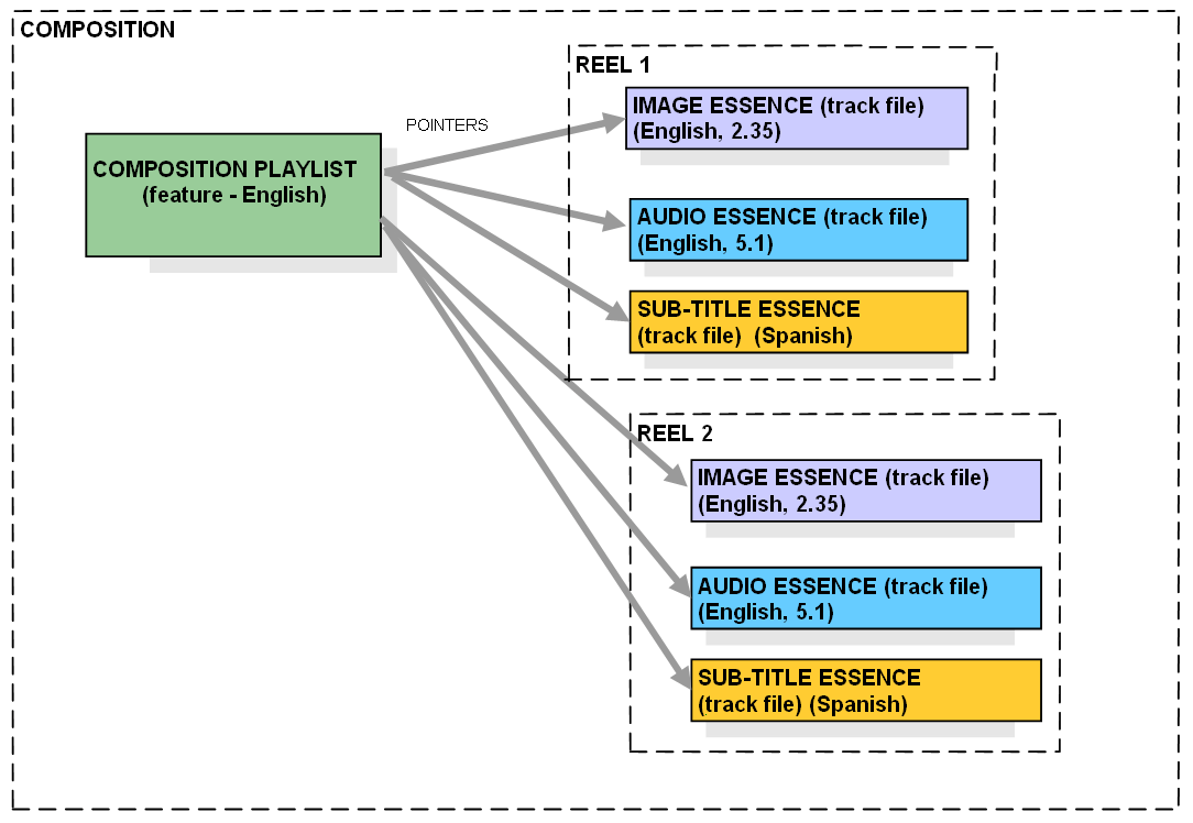
or any other essence and/or metadata tracks. A Composition Playlist specifies the
sequence of track files that create sequence conceptual reels into a composition.
This is illustrated in Figure 5. A Composition Playlist
is created in the Digital Cinema mastering process to assemble
a complete Composition.
This Composition consists of all of the essence and metadata required for a single
presentation of a feature, or a trailer, or an advertisement, or a logo. A single
Composition Playlist contains all of the information on how the files are to be played,
at the time of a presentation, along with the information required to synchronize
the track files. A Composition Playlist could consist of one reel or many reels. For encrypted essence, the
Composition Playlist shall be digitally signed such that
modifications to the Composition Playlist (and/or the associated composition) can
be detected. There is a separate Composition Playlist for each version or language audio track
of a motion picture/feature (composition). For example, a DCP of a feature film for
the European market with French, Italian, German and Spanish audio tracks would contain
four separate Composition Playlists, one for each sound track.
At the exhibition site, the Theater Management System (TMS) or Screen Management System
(SMS) assembles the Show Playlist. A Show Playlist is created from individual Composition
Playlists. The Show Playlist can also be created either on-site or off-site and interchanged
as a file to one or more Screen Management Systems. One could have multiple Playlists
as well. Figure 6 is an example of a Show Playlist consisting
of multiple Composition Playlists.
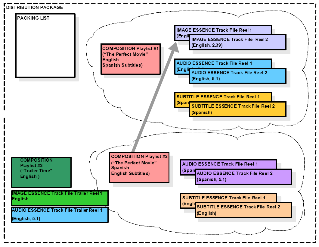
The final element in the Packaging system is a Packing List for the distribution package.
The Packing List contains information and identification about each of the individual
files that will be delivered in a Digital Cinema Package (DCP). This allows for asset
management and validation, including cryptographic integrity checking, for the received
DCP. A feature can be sent in a single DCP or multiple DCPs and therefore could be
listed in one or more Packing Lists. The Packing List can be sent ahead of the DCP,
for asset management purposes. A diagram of a Packing List structure is shown in
Figure 7: Example Distribution Package.
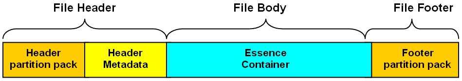
The Sound and Picture Track File is the fundamental element in the Digital Cinema
packaging system. The Sound and Picture Track File structure and requirements are
defined by the essence or metadata that they contain. Each of these essence or metadata
containers could be image, sound, subtitle (Timed Text and/or subpicture) or caption
data. However, each track file follows the same basic file structure. A track file
consists of three logical parts: the File Header, the File Body and the File Footer
as shown in
Figure 8: Example Track File Structure.
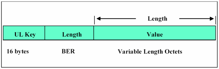
The file structure is further broken down into logical data items as defined in [SMPTE
336M Data Encoding Protocol using Key-Length-Value]. The KLV Coding Protocol is composed
of Universal Label (UL) identification Key (UL Key), followed by a numeric Length
(Value Length), followed by the data Value as shown below in
Figure 9. One or more
of these data items are combined to form the logical parts shown above.
Each track file is required to be a self-contained element, such that its essence
or metadata can be understood and presented as it was packaged by a compliant decoder.
The information is required to be located in the predetermined specified area. The
Track File is required to contain the following minimum information:
Required metadata for unique asset identification
Required metadata for decompression (optional)
Required metadata for decryption (optional)
The following information is required to be configured in a human readable format:
Essence physical format description (e.g., 4096 x 2160)
Essence title asset information (e.g., The_Perfect_Movie_English_R2)
Track Files of the same essence type and playback devices are required to support
artifact-free splicing at any frame boundary, allowing the assembly of a continuous
data stream from multiple Track Files. The playback device is required to perform
sample accurate splicing of Sound Track
Files.
Each Track File is required to provide for encryption and methods to authenticate
the data, if the content provider chooses to use such methods. In addition:
The essence container is required to allow encrypted data, while the rest of the Track
File metadata is left unencrypted.
At any point in the delivery chain, it is required to be possible to detect whether
any accidental or intentional alteration has occurred.
Each Track File is required to provide a method for verification of file integrity
that can be easily determined at any step of the delivery process. In addition:
It is encouraged that missing or corrupted data be easily identified.
Track Files are encouraged to be subdivided into smaller segments, which have individual
authenticity/error-check codes. This facilitates a decision as to whether the file
is so corrupt it cannot be played, or whether it is safe to proceed with playback
while requesting a replacement Track File.
Synchronization with other Track Files is encouraged to be verifiable.
The Operational Pattern is required to support random access to the nearest integer
minute. Random access to individual frames is neither required nor desired.
A restart occurs as a result of a stop or pause in the system while executing a Composition
Playlist. The system may be restarted at any frame prior to the frame at which it was stopped
or paused. It is required that a restart be logged by the Security Manager, provided
that the essence (either image, audio or subtitle) is encrypted.
A track file is required to contain essence of a single essence type (e.g., audio,
image, subtitles). While a Track File can, for instance, contain all audio channels
for a given language, additional languages are required to be stored in separate track
file. The Composition Playlist will select the correct Track Files to play a requested
version of the movie (composition).
MXF Track File Encryption shall be compliant with SMPTE 429-6 D-Cinema Packaging –
MXF Track File Essence Encryption. The following requirements clarify the use of SMPTE
429-6 with this specification. For the purpose of this section, a frame is defined as an image frame time,
for example
24 FPS or 48 FPS.
Each reel shall use a single cryptographic key for all frames within the sound or
picture Track File.
The integrity of each frame of sound and picture essence shall be verifiable using
the HMAC-SHA1 algorithm. The optional Message Integrity Code (MIC) element of SMPTE
429-6 shall be present.
There shall be a method for verifying that all frames within a sound and picture track
are played in correct sequence. The optional TrackFileID and SequenceNumber elements
of SMPTE 429-6 shall be present.
An Image Track File contains the image essence data and its associated metadata. Each
Image Track File contains compressed image data and, optionally, may be encrypted.
The following are requirements for an Image Track File.
The Image Track File is required to begin and end with complete frames that allow
for splicing. Frames are defined to be image frames such as 24 FPS (1/24 sec) or 48
FPS (1/48 sec). The image data within the Track File shall be wrapped using KLV on
an image frame boundary.
The Track File is required to support Constant Bit Rate (CBR) compression and Variable
Bit Rate (VBR) compression, within the constraints of the specified code stream for
the reference decoder (see Section 4. Compression).
The Audio Track File is required to begin and end with complete frames that are associated
with its Image Track File to allow for a clean transition between reels. The audio
data within the Track File shall be wrapped using KLV on an image frame boundary.
A Subtitle Track File contains, for example, the Subtitling essence data and its associated
metadata. Each Subtitle Track File may contain any combination of text, font references,
and image references.
It may be necessary to package auxiliary data or nonstandard essence for a specific
use case. In these cases the extension shall not interfere with the proper handling of the DCP
by an otherwise compliant system. Extensions shall adhere to the requirements given in this
specification and the Auxiliary
Data requirements of[SMPTE ST429-14: "D-Cinema Packaging -- Aux Data File"].
Composition Playlists (CPL) are textual lists that define how elements of Digital
Cinema Compositions are played back in a presentation. The content owner creates the
Composition Playlist in a post-production environment.
For encrypted essence, the
Composition Playlist shall be digitally signed such that
modifications to the Composition Playlist (and/or the associated composition) can
be detected.
The Composition Playlist is required to contain the following human readable information
in English (default) but can be provided in other languages as well.
For encrypted essence, the Composition Playlist shall be digitally signed such that
modifications to the Composition Playlist (and/or the associated composition) can
be detected. In support of this, the CPL assets "KeyID" and "Hash" elements shall
be present in the CPL track file asset structure.
The Distribution Package has two major components. One is the Package itself, which
includes all of the Track Files and the other is the Packing List. These are all of
the elements required for a complete delivery to the theater Digital Cinema system.
It is technically possible to include engagement-specific licenses and keying information
in a Package in the form of opaque metadata, but this is not recommended for general
usage.
A Distribution Package can contain a complete feature composition or a set of compositions.
Alternatively, it can carry as little as a single file to update one reel’s subtitle
or sound track.
The distribution method is required to provide digital signatures to allow the recipient
to verify integrity of the Packing List and the enclosed files. In particular, where the DCP contains
encrypted essence files, the Packing List shall
be digitally signed.
Preparation of Packing Lists is a distribution fulfillment or transport function.
Therefore, the digital signatures come from these entities, not the content-owner
who mastered the files. Packing List security functions do not verify the authenticity
of the content, only the intent of the delivery agent.
Content authenticity is verified
through signed Composition Playlists and validated
Key Delivery Messages.
The Packing List is required to use XML data format with XML signature (digital signature). It should be in
English (default) but can be provided in other languages as well.
The following data fields are required to be included in the Packing List for each
file in the Package:
UUID
Annotation Text parameter (optional), if present, is a free-form, human readable annotation
associated with the asset. It is meant strictly as a displayable guidance for the
user
File Integrity check (hash) for each file in the distribution package
Size of the file in bytes
Type (e.g., Packing List, Playlist, Track File, opaque security data)
Original File Name
The following fields are required to be included in the digital signature section
of the Packing List:
Signer parameter uniquely identifies the entity, and hence public key that digitally
signs the Packing List.
Signature parameter contains a digital signature authenticating the Packing List.
Transport refers to the movement of the packaged Digital Cinema content. This can
be accomplished in many ways, such as physical media, Virtual Private Network (VPN),
or satellite. This section will describe any requirements for the transport of packaged
content.
The transport of Digital Cinema content can be accomplished in many different ways.
The Distributors will select the method that is both economical and technically robust
to ship their content to the theaters. This can include the use of physical media
or through transmission (e.g., satellite, fiber, copper). Any selected method is required to provide for a
secure environment for the content
as well as no corruption of the data. Segmenting of the packaged content can occur to accommodate fixed
media or bandwidth
constraints.
Independent of the transport method, the output interface of the transport system
is required to be ingested into the Digital Cinema Storage in the theater.
The ingest interface shall comply with either Clause 34 or Clause 44 of [IEEE 802.3-2005]
for either 1000 Mb/s or 10 Gb/s operation, respectively.
Theater Systems for Digital Cinema incorporates all of the equipment required to make
a theatrical presentation within an auditorium located within a Theater complex. This
encompasses projectors, Media Blocks, Security Managers, storage, sound systems, DCP
ingest, theater automation, Screen Management System (SMS) and Theater Management
System (TMS). The Screen Management System (SMS) provides the theater manager a user
interface for local control of the auditorium such as start, stop, select a Show Playlist
and edit a Show Playlist. At a higher level is the Theater Management System (TMS).
The TMS can control, supervise and report status on all of the equipment in the Theater
as well as perform all the duties of the SMS. This section will define the requirements
and interconnectivity of a TMS and multiple SMSs within a theater complex.
For the purpose of documenting the specific requirements and specifications for a
Digital Cinema Theater System, it is helpful to divide the system into a set of components.
The specifications and performance requirements for each of these components will
be described in the following sections:
Screen and Theater Management Systems – The human interface for the Digital Cinema
System
Theater Systems Architecture – The equipment and interconnect within the Theater
Theater Systems can have a wide range of responsibilities. They are required to provide
a theatrical presentation in a timely manner along with controlling the environment
in which it is presented. To simplify this complex system, each major component of
a Digital Cinema Theater System is reviewed and shown how they interconnect. The human
interface of the single screen system is the Screen Management System (SMS). It is required that there be one
SMS for each auditorium. The Screen Management System (SMS) provides user interface to control (start,
stop,
pause, load playlist, etc.) a single auditorium. The Theater Management System (TMS)
allows a theater manager to control many or all auditoriums within a theater complex
from a central location. This is the interface that allows for control, show programming,
troubleshooting, asset management and status of the Digital Cinema equipment. There
are many different scenarios for the implementation of the SMS and the TMS.
A key part of the Digital Cinema system is reliability. In the realm of Digital Cinema, the presentation
should not be interrupted, except
in the event of a catastrophic failure of the Digital Cinema system (e.g., loss of
power) or a natural disaster. There will be cases where equipment will fail (such
as happens now with traditional 35mm film equipment). However, the time between failures,
and the speed at which it is repaired, is encouraged to be no worse than those for
traditional 35mm film equipment.
Each individual theater system is required to have a Mean Time Between Failure (MTBF)
of at least 10,000 hours.
A failed or malfunctioning unit/component is required to be capable of being diagnosed
and replaced within 2 hours, exclusive of the time needed to order and to deliver
the replacement component(s). Design of a system is required to allow repair of any
failed unit/component within two hours.
The system is required to provide monitoring and diagnostic checks and provide for
status, monitoring, alignment and calibration. This can be done locally or through
remote control.
The system is required to provide for intra-theater movement of content within a multiplex
facility. Emergency moves (e.g., equipment failure) between auditoriums are required
to allow playback to start within 15 minutes or less after the start of the movement.
The Digital Cinema Theater System is encouraged to require only a reasonable level
of computer operation knowledge or training for the basic operation of the system.
The computer-based user interfaces are required to be simple and intuitive.
The theater is required to provide an adequate environment for the equipment, with
an operating temperature range of 10-35°C and operating Humidity of 10% to 85% Non-Condensing.
The central and/or local storage system is required to have the capacity to hold at
least 1 TByte of usable storage per screen, where a TByte equals 1,000,000,000,000
bytes.
Theater systems equipment is required to implement all the security requirements as
specified in Section 9. Security. These requirements enable the necessary functions and features for a
reliable and
persistent environment to protect content and Security Data, and support the required
forensic processes that stakeholders require.
The Show Playlist is the list that the Exhibitor assembles to complete a presentation
in the theater. The Show Playlist has the following requirements.
The Screen Management System (SMS) is required to allow the theater staff to function
similar to traditional theater operations. The workflow does not need to radically change to support
Digital Cinema presentations.
Digital Cinema content will arrive at the theater via fixed media, or through other
means of transport, and will be loaded into central or local storage. The staff will
then assemble a Show Playlist using a computer Graphical User Interface. This Show
Playlist could include advertisements, logos, previews and a main feature. The staff
will then direct the show to the screen and let the SMS begin the show by local or
remote control.
The Screen Management System provides a user interface to control (start, stop, pause,
load playlist, etc.) a single auditorium. The Theater Management System (TMS) allows
a theater manager to control many or all auditoriums within a theater complex from
a central location.
At the beginning of this section, fundamental requirements were listed that would
allow theaters to operate as they have been for some time. This section will elaborate
on some of these and other requirements, as they affect the SMS and TMS.
The SMS and TMS are required to support multiple levels of user accounts. The following
is an example of multiple accounts: Projection, Show Manager, Super-user, and Administrator
with password-protected appropriate log-ons.
Projection – Required to be able to perform the following functions
Browse and activate current shows
Play content, including starting and stopping playback
Assemble shows
Show Manager – Required to have access to the following functions
All projection functions
Assemble or Delete Shows to/from storage
Import/Delete Content to/from storage
Super-user – Required to have access to the following functions
All Show Manager functions
User Management
Theater System Setup
Administrator – Required to have access to the following functions
Content can be received by physical media or via a network. The theater systems are
required to allow multiple motion pictures and related content to be delivered to
a theater in a timely matter. The theater systems are also required to provide a method
to verify that the data is complete and whether or not it has not been corrupted.
The SMS and TMS are required to allow an authorized user to search for content and
provide a method for the movement and deletion of content, within a screen or multiplex
facility, while the system is in operation. As an example, this would include simultaneous content load-in
and playback. This
movement could consist of many different examples of operation such as:
Downloading content while playback of presentations are in progress
Movement of content from a central storage to local storage while other content is
in playback
Deleting content while other content is in playback
The SMS or TMS is required to warn and not allow deletion if the content is in use
or part of a current Show Playlist.
The SMS or TMS is required to provide a deletion process that removes all of the content,
key information, and playlists associated with the composition.
An electronic method is required to assemble trailers, feature presentations and other
content in the creation of shows. At a minimum, a standard method is required to electronically
identify the content to the SMS, TMS and the Security Manager (SM) to allow the show
to be assembled and played back. This method of identification is embedded within the packaging format as
metadata.
(See Section 5. Packaging)
Operationally, the SMS and TMS are required to provide the user with a method of creating
a Show Playlist. This method provides for the following:
A method of building shows is required to allow only authorized personal to build,
save and transport the Show Playlist.
A method is required to use the validity/expiry method, so that one can check that
one has the security devices and keying parameters required for playback.
A method is required to make it possible for a Show Playlist to be provided via an
external source.
A method is required to provide a means for inserting a black screen and silence between
content. The Media Block is required to be able to transition modes without displaying
a roll or similar artifacts during a transition between clips in a playlist or between
playlists.
Show Playlists can consist of both encrypted and non-encrypted content.
The Show Playlist can be communicated in whole to the Media Block, whereupon it is
then stored and subsequently executed within the Media Block (Content Data Pull Model).
The Show Playlist can be executed within the SMS and communicated to the Storage and
Media Block one command at a time (Content Data Push Model).
A method is required to provide for the insertion of cues. These cues allow the automation system to
perform its tasks at event boundaries, such
as start of feature and start of end credits.
The Automation System is required to communicate events to and from the screen equipment. These can
be light dimmers, curtains, or other systems within an auditorium. These events or cues are programmed
within the TMS or the SMS, and initiated by either
the SMS or the Automation depending on which unit is master and which is slave. All
of the event types are pre-programmed to have certain effects on the system. These events, at a minimum, are
required to be recognized by all systems and are
listed below:
Have full content play functionality (e.g., make playlists active, stop, start, start
play) at any reel break point in a playlist.
Handle power interrupted while playing content. When the system is next started, it
is required to inform the user that playback was abnormally interrupted during the
last play, and offer the user the ability to restart playback at a point prior to
the failure (see Section 5.3.1.11. Random Access and Restarts). The system should also log such
events.
Have no interruptions during playback (glitch-free).
Adjust the delay of audio ±5 image frames in 10 msec increments of all presentation
content to the image.
The following table depicts situations and events related to the Theater Management
System (TMS). These events do not affect the security system and are known only to
the Theater Management System. In addition, the Theater Management System has the
ability to have pre-showtime knowledge of events in the security system by directing
the Screen Management System to query the Security Manager.
Table 8: Examples of Theater Management System Events🔗
Item, Observation or Issue
Approach
Log data collected from auditoriums
TMS controls and can check collection status
Equipment installation and locations
TMS knows about and controls installations
Auditorium scheduling
TMS knows scheduling information
The examples in Table 8 are outside of the knowledge or control of the security system.
The Theater Management System may have the capacity to execute such functions or make
records of various activities under its control. Under a private agreement between
the Exhibitor and the Distributor, data collected by the Theater Management System
could be made available.
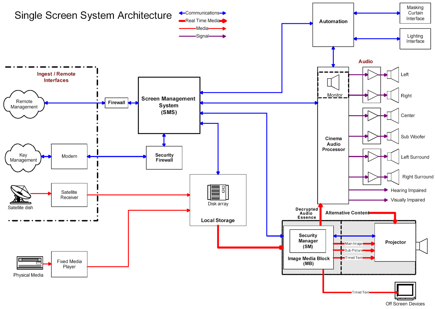
A Digital Cinema Theater System includes several component systems: ingest, storage,
Media Block, security, projection, audio system, Theater Management System, Screen
Management System and automation. An example of a single screen installation is shown
in Figure 10.
Ingest is the process of receiving content and security information at the theater
level. These are the devices that connect to and from the outside world. The following
is an example list of such devices split into two groups. The first group has to do
with content while the second group is for security and control.
Content:
Satellite receiver(s) (with cache or local storage)
Terrestrial fiber network(s) (with cache or local storage)
Once a complete DCP has been ingested, the TMS or SMS is encouraged to verify that
a KDM is available and displays the time window for showing the content. A TMS or
SMS show schedule can display conflicts between the KDM and the scheduled showings.
The TMS or SMS is encouraged to alert the user when a KDM will expire within 48 hours.
Except for security messaging, the interfaces to the outside world can use any method
or physical connection. Inside the theater structure, the architecture is encouraged to break down into two
types of interfaces, one for the content and one for control/status and key exchange.
The content ingest interface is required to be Gigabit Ethernet [IEEE802.3ab (copper)]
or [IEEE802.3z (fiber)] interface.
Theater facilities are required to provide a connection that will be available 24/7
for security communications (all ETM and log data reporting). It is theater management’s
decision as to whether this connection is dedicated. However
it will be recognized that for some operational situations (e.g., receiving new KDMs),
it may be important to have priority access to this connection for security communications.
Additional alternative means of security communication can be implemented by agreement
between the parties.
Theater networks are required to protect the security system from the threat of external
and internal network-born attacks by the installation of appropriate firewalls. Because there will be many
variations in network designs, it is impossible to define
specific solutions as part of this specification. Exhibition operators are encouraged to solicit competent
network security engineering
assistance as part of their facility network design efforts.
Content storage can be arranged into two basic configurations or a combination of
the two. One is known as local storage and the other is central storage. Local storage
is a configuration where the storage is located at each screen. Central storage is
a configuration that has all of the storage of content in a central location for all
of the screens in a multiplex. There can also be combinations of central and local
storage.
The most important aspect of the storage system is reliability. There are a number
of RAID configurations that will provide storage redundancy and therefore storage
reliability. The storage system is required to provide redundancy such that should a single hard
disc drive fail, the system will continue to play with no visible or audible interruptions
or artifacts.
Central Storage implies that packaged content for a multiplex may be stored in one
location. Central Storage may allow for multicasting of the content.
If only Central Storage architecture is used, careful planning is required to be done
to ensure that it does not have a single point of failure, including the network.
In this type of implementation, the Central Storage is required to also provide the
capability to sustain the peak bit rate of all screens being fed simultaneously, along
with ingest.
Local storage implies a single storage system for each screen. Local storage is required to be able to
sustain the bit rate required for the playback
of all content for that screen.
A combination of central and local storage for a multiplex can be the best solution.
The central storage can be used for ingest of material and redundancy of content,
while the local storage is encouraged to hold just the content required for the immediate
presentation(s).
The storage system is required to provide enough output to support a continuous stream
of 307 Mbits/sec for compressed image, uncompressed audio (16 channels, 24 bit sample,
96 kHz) and subtitle data to allow for non-interrupted Digital Cinema playback.
Excluding storage necessary for redundancy, the storage system is required to provide
for, at a minimum, the storage of three features (including pre-show content) per
screen (one feature currently showing and a second or upcoming feature). Shown in
Table 9: Example of Storage Capacity for one 3-Hour Feature (12 bits @ 24 FPS),
are some example storage requirements. The numbers are based on:
One three-hour feature
20 minutes of pre-show material at the same resolution
16 channels of uncompressed audio at 48 kHz at 24 (AES3) bits
3,000 sub pictures in PNG file format
3,000 Timed Text lines
Table 9: Example of Storage Capacity for one 3-Hour Feature (12 bits @ 24 FPS)🔗
Average Bit
Rate
(Mbits/sec)
3 Hour
Image
(GBytes)
3 Hour
Audio
(GBytes)
20 min.
pre-show
(Gbytes)
Sub
Picture
(GBytes)
Timed
Text
(GBytes)
3 Hour
Total
(GBytes)
250
337.500
2.074
37.500
0.300
0.001
377.374
200
270.000
2.074
30.000
0.300
0.001
302.374
125
168.750
2.074
18.750
0.400
0.001
189.974
100
135.000
2.074
15.000
0.600
0.001
152.674
80
108.000
2.074
12.000
0.800
0.001
122.874
Image size:
Calculated by: {Average or max bit rate (Mbits/sec) * hours * 60 min/hour
* 60 sec/min} / {8 bits/byte *1000} the results is in GBytes
It is required that image and audio essence on storage devices retains the original
AES encryption, if present during ingest. It is required that decrypted plaintext
(image or audio) essence is never stored on the storage system.
Another key component in the playback chain is the Media Block. One or more Media
Blocks are responsible for converting the packaged, compressed and encrypted data
into raw image, sound and subtitles.
Depending upon implementation, both security and non-security functions take place
within Media Blocks. Security functions of Media Blocks (those functions which process
plain text essence or Security Data such as decryption keys) may take place only within
physically secure perimeters called Secure Processing Blocks (SPB). The more general
functions of the Media Block and variations on implementation are described here.
Not all such functions are required to be within an SPB. Detailed security requirements
of Media Blocks are discussed in Section 9.4. Theater System Security.
The Image Media Block can be implemented in a server configuration, as shown in Figure 11.
This is where the storage and the Image Media Block are closely coupled. In this
configuration, the content data is then pushed to the projector. In this configuration, Link Encryption is
required to protect the uncompressed content.
The Image Media Block can also be implemented as a component within the projection
system. This provides the option of not requiring Link Encryption. In this configuration,
the Image Media Block may use a push or pull method to process essence data from storage,
as shown in
Figure 12: Media Block in Projector Configuration.
[5]
Figure 12: Media Block in Projector Configuration🔗
In addition to the two single Image Media Block (IMB), single projector configurations
shown above, this specification provides for Multiple Media Block (MMB) configurations
to support multiple projectors and/or the use of an Outboard Media Block (OMB) within
the projection booth. See Section 9. Security for details of MMB and OMB requirements
and operation.
Note: Due to the dynamic nature of security technology, DCI reserves the right, at
some future time, to update requirements and may require changes to Digital Cinema
systems as situations warrant.
A Media Block is the device that converts, in real time, the packaged content data
from storage into data for playback to downstream devices. The one or more Media Block(s) of the projection
booth are required to playback the
image, audio and other time-dependent content in a manner that presents a synchronized
performance to the audience. Synchronization requirements are as follows:
Synchronization of audio and on-screen text to image shall be frame accurate.
Synchronization of audio objects shall be accurate to within 10 microseconds (sample
accuracy at 96 kHz).
The synchronization signal shall include information that represents the current position
within the show timeline and shall be accurate to within 10 microseconds.
"Locate and play" shall be supported.
The synchronization signal shall be defined separately from any essence it may be
asked to synchronize, and able to sync multiple media blocks regardless of the essence
they are handling.
The synchronization signal shall be compliant with SMPTE ST 430-14 D-Cinema Operations
-- Digital Sync Signal and Aux Data Transfer Protocol.
The main function of a Media Block is to provide a secure environment within which
to perform content essence decryption. In support of this Media Blocks shall contain a Security Manager, media
decryptor(s)
and (as applicable) associated forensic markers. Link Encryption shall be applied
to image essence if the associated Media Block is not contained within the projection
system.
7.5.4.2.3. Image Link Encryption and Decryptor Block 🔗
If the Image Media Block is not physically located in the same secure container as
the projector, then the Image Media Block is required to provide link encryption to
the projection system to protect image essence per Section 9.4.4. Link Encryption. At the projector, a
Link Decryptor Block is required to decrypt the image essence.
The Link Decryptor Block is required to provide SPB type 1 physical protection for
link decryption, the associated security keys and logging functions.
Any packaged content that comes from storage is required to contain all of the content
data required for the presentation and file integrity. The first job of the Media Block is to arrange the
track files into their appropriate
modules and to provide a timely supply of data to the next process. The content can arrive completely unpacked
or partially unpacked depending upon the
system’s storage method.
The subpicture renderer, a module that converts the subpicture file into the DCDM*
image file with an alpha channel overlay, can be located in the projector or the Media
Block.
The Timed Text renderer, a module that converts Timed Text data into the image file
with an alpha channel overlay, can be located in the projector or the Media Block.
The Media Block is required to interface on three levels with the rest of the system. One level deals with
the packaged Digital Cinema content. The next level is the raw
essence output for the projector, the audio processor and any special devices for
the automation system. The third level is the control and status of the Media Block
playback system. These interfaces are noted below.
Packaged Data – The packaged content requires a standard data interface that could handle bandwidths
up to 307 Mbits/sec for the composition data. This may be a Gigabit or 1000Base-T
Ethernet [IEEE 802.3ab (copper)] or [IEEE 802.3z (fiber)] interface.
Uncompressed Essence – The raw essence data requires a real time data interface with extremely high
bandwidths. The interface will depend on the physical location of the Media Block and the type
of essence that the interface carries.
Main Image – This streaming data interface is required to handle data rates up to 10
Gbits/sec.
(See Section 8. Projection for details.)
Subpicture – This streaming data interface is required to handle data rates up to 20
Mbits/sec.
This can be accomplished by the use of a standard 100Base-T Ethernet [IEEE 802.3]
interface.
Timed Text – This could be a streaming data interface depending on the buffer capability
of
the projector. It is expected that this interface can also use a standard 100Base-T
Ethernet [IEEE 802.3] interface that can handle data rates up to 500 Kbits/sec. It is encouraged that there be
at least two of these interfaces from the Media Block,
one to feed the projector and the other to feed off-screen devices.
Audio – This interface is required to stream multiple digital audio channels to the Cinema
Audio Processor. This is required to be in an AES3 format.For worst-case audio bandwidth, 18.5
Mbits/sec is required (16 channels * 24 bit sample
* 48 kHz). 37 Mbits/sec is recommended (16 channels * 24 bit sample * 96 kHz = 37 Mbits/sec).
Security Messaging –
The Media Block is required to communicate standardized security
messages (see Section 9.4.5. Intra-Theater Communications) via a standard 100Base-T Ethernet [IEEE 802.3]
interface to the projector and remote
Secure Processing Blocks.
This communications facility is referred to as the intra-auditorium security
network
and it may physically be part of other/existing auditorium networks, which carry other
types of traffic (e.g., command, control and status). However, it is distinguished in that security messaging
is required to utilize Transport
Layer Security (TLS) at all times. See Section 9.4.5. Intra-Theater Communications.
The Projection System is required to change digital image data into the light that
appears on the screen. The projection system is required to support many interfaces and different
Digital
Cinema system architectures. One of these architectures includes the Media Block (described above)
installed
in the projector. In this type of architecture, all of the content is ported through
a single data interface. When the Media Block is external to the Projector, Link Encryption is required.
The corresponding Link Decryption Block is required at the projector interface.
Alternative content can come from an external interface, even when the Media Block
is present inside the projector.
The Projection System not only provides the main image on the screen, it can provide
subtitles, open captioning, and still pictures. This requires extra interfaces from
the Media Block, if the Media Block is not installed in the projector. These interfaces
are noted below. (For the complete interface specification refer to Section 8. Projection.)
Subpicture – The subpicture (bit mapped image data with alpha channel) information will need either
a separate interface into the projector, or the Media Block is required to overlay
the subpicture with the main image and send it through the main image interface.A subpicture interface
is required to be a 100Base-T Ethernet [IEEE 802.3] interface
with enough sustained bandwidth to support subpictures at up to 24 FPS for
4K content and 24 FPS or 48 FPS for 2K content.
Timed Text – Information can also enter into the projector through a data port or
be rendered
and overlaid in the Media Block. The interface is required to be a 100Base-T Ethernet [IEEE 802.3]
interface.
Control and Status – The projection system is required to also provide a 100Base-T Ethernet [IEEE 802.3]
data interface that can receive control information and send status to the Media Block
and SMS.
The Audio System delivers the sound of the theatrical presentation to the audience.
It is responsible for receiving the uncompressed digital audio from the Media Block,
converting it to analog and directing it to the proper speakers for translation to
acoustic energy. The system is required to provide the capability for 16 channels of audio playback.The
presentation is required to provide, at a minimum, a 5.1 audio format, (Left,
Center, Right, Low Frequency Effects, Left Surround and Right Surround). An audio format of 7.1 can also be
provided. The undefined channels can include
a Hearing Impaired and/or a Visually Impaired channels as well.
The Cinema Audio Processor can provide the digital audio conversion and the channel
mapping. Its other duties can include playing the intermission program or music (often
called non-sync) and allowing for monitoring in the projection booth.
The Audio System requires several interfaces. The main interface deals with the digital
audio and the other interfaces deal with status and control. These interfaces are noted below.
Digital Audio – The digital audio is delivered from the Media Block to the Cinema
Audio Processor.
This is a real time digital audio link that shall have the capacity for delivering
16 channels of digital audio at 24-bit 48 kHz. It is encouraged that this link support 96 kHz. For purposes
of clarity, the MB shall be capable of processing 16 channels of 24 bit audio at 48 kHz, and is encouraged
to be capable of processing audio similarly at 96 kHz. This link is required to follow [AES3-2003] recommended
practice for serial transmission
format for two-channel linearly represented digital audio data.
Control and Status – The Cinema Audio Processor is encouraged to also provide a 100Base-T Ethernet
[IEEE
802.3] interface that can receive control information and send status to Automation
and/or
SMS depending on the existing Automation in the theater.
A Screen Automation System can interface with life safety, motor controlled curtains,
motor controlled masking, the dimmers for the lighting, existing 35mm film projectors
and possibly to other devices such as the Cinema Audio Processor, and/or special effects
devices. One of the challenges of Digital Cinema is to interface with the many different
Automation devices installed presently in the theaters.
The automation interface is a variable that is different depending on the manufacturer
of the installed system. This could range from contact closures to proprietary interfaces.
The Theater System is required to translate Digital Cinema cues into something that
the automation system understands, and reciprocally, is required to translate the
automation information into something the SMS understands.
Each auditorium is required to have a single dedicated Screen Management System (SMS). The Screen
Management System provides a user interface to theater management for
local control of the auditorium, such as start, stop, select a Show Playlist and edit
a Show Playlist. In addition to control, the Screen Management System can monitor
and run diagnostics on equipment within the auditorium and provide such status information
to the exhibitor. The Screen Management System is required to operate in one of two modes, local or
remote.
The following table depicts situations and events related to the Screen Management
System.
Table 10: Examples of Screen Management System Events🔗
Item, Observation or Issue
Approach
Corrupted Movie Received
SMS can validate received DCP
Valid Composition Playlist Received
SMS can validate received CPL
Movie prepped for playback is modified
SMS can check prepped movie against CPL
Playback time associations of Trailers-Movie
SMS knows show playlists and execution statistics
The examples in Table 10 are outside of the knowledge or control of the security system.
Under a private agreement between the exhibitor and the distributor, the Screen Management
System may be required to execute functions or make records of such activities under
its control.
Many Theater Systems will be part of a larger multi-screen facility. A single TMS
for Digital Cinema operations is expected to support all multiplex configurations.
Figure 13: Multiplex Theater System Architecture below demonstrates an example architecture of one
of these systems from an interface
prospective. This section will consider the requirements and interfaces of a large
networked system. There are two main interface components of this larger system. The
first is the Media Network and the second is the Theater Management Network.
The Media Network is a high bandwidth, switched interface, made up of media interfaces,
Disc Arrays and Media Blocks. The Media Network is required to support sustained rate of 307 Mbits/sec for
compressed
image (250 Mbits/sec), audio (37.87 Mbits/sec - 16 channels, 24 bit sample, 96 KHz)
and subtitle data (subpicture 20 MBits/sec) for each screen. Additional data bandwidth is needed for
ingesting new content and control/monitoring.
Not all multi-screen complexes will have Theater Management Networks. When present,
the Theater Management Network is a low bandwidth, shared interface, made up of Theater
System devices and an Ethernet distribution system. This is required to be accomplished using 100Base-T
Ethernet [IEEE 802.3]. This network
is required to support all of the control, configuration, security,
software upgrades, testing and status of the Theater Systems.
The Theater Management Network can be sub-divided into two main categories of communications:
Operational communications – The sending of commands and data to the Theater System
devices and receiving status back from those devices. TCP/IP is required to be the protocol to send commands
and configuration. SNMP/UDP/IP
(Simple Network Management Protocol over User Datagram Protocol over Internet Protocol)
can be used for status of the equipment.
Security communications – This messaging supports pre-playback, playback and post
playback operations and thus interfaces with the security subsystem(s). Such communications may take place over
the same networks as above. However, security
communications are required to employ Transport Layer Security (TLS) per the security
requirements of Section 9. Security.
The following is a list of devices and examples of typical communications:
7.5.9.3.2. Screen / Theater Management System (SMS/TMS) 🔗
Playback – Commands and Status, Material IDs, Asset Management
The Projection System is an essential part of the Digital Cinema System. Its job is
to change digital image data into light that appears on the screen. This section is
broken into parts to help define the requirements, interfaces and performance specifications.
Bearing in mind that a core goal is to have the mastering room image seen by the public,
it is intended that the projection system should faithfully replicate the DCDM as
is described in Section 3. Digital Cinema Distribution Master.
For the purpose of documenting the specific requirements and standards for a Digital
Cinema Projection system, it is helpful to divide the system into a set of components.
The specifications and performance requirements for each of these components will
be described in the following sections:
Digital Cinema presents a challenge to create a versatile projection system. Throughout
this system, some basic requirements are needed and are stated below.
The sampling structure of the displayed picture array (pixel count of the projector)
is required to be equal to or greater than that of the specified image containers
(either 4096 x 2160 or 2048 x 1080).
The projector is required to display either a native resolution of 4096x2160 or 2048x1080.
If the projector's native resolution is 4096x2160, and the incoming spatial resolution
of the content is 2048x1080, then the projection system is required to perform the
up-conversion of 2048x1080 content to 4096x2160. All spatial conversions are required
to be done at an exact ratio of 2:1 in each axis, i.e., a projector with a horizontal
pixel count of slightly higher than the image container is required to not convert
the projected image beyond the image container to fill the array, nor is an image
to be converted to something less than the 4096x2160 or 2048x1080 image container
size.
Should electronic image resizing or scaling be used to support a constant height projection
or constant width projection theater environment, then it is required that the image
resizing or scaling does not introduce visible image artifacts. It is intended that the projector project
the full horizontal pixel count or the
full vertical pixel count of the image container.
A Forensic Mark is required to be inserted in real time into the content at the earliest
point after decryption and prior to the content data being present on any data bus
outside the Media Block (see Section 9.4.6.2. Forensic Marking Operations).
In the preferred implementation, the projector is required to provide an area for
a Media Block to be installed. If the Media Block is installed external to the projector,
then a link encrypted interface is required to ensure that no Digital Cinema content
is in the clear.
The Digital Cinema projector is one of the principal elements in the system. It is
perceived that projector technology will continue to change and develop with time.
There are several items affecting the projection system: color space, resolution,
brightness, contrast and interfaces. The projector is required to convert from the incoming X’Y’Z’ color space
to its native
color space. The projector is required to support more than one spatial resolution and frame rate.
A Reference Projector is used in the mastering process for creating the Digital Cinema
Distribution Master (DCDM), with the target performance parameters and tolerances
included in this chapter described below. Test patterns and measurement procedures
are defined for measuring these performance parameters. It also describes a controlled
environment for the mastering of projected images. The goal is to provide a means
for achieving consistent and repeatable color quality.
8.3. Projected Image and Viewing Environment for Digital Cinema Content 🔗
This section provides requirements defining the reference input to a Digital Cinema
projector, the viewing environment, and output display characteristics for mastering
and theatrical environments. These requirements are provided to ensure a single inventory
distribution will be input compatible with any brand projector and that the projector
output will be predictable, based on the standard format input. Nominal reference
points plus tolerances are provided.
The projector is required to support the image structures, aspect ratios, file formats,
and frame rates as specified in Section 3.2. Image Specification. The projector can support other
image structures, aspect ratios, file formats, and
frame rates as determined by the individual manufacturer.
8.3.3. Environment, Image Parameters and Projected Image Tolerances🔗
The SMPTE published recommended practice [SMPTE RP 431-2: D-Cinema Quality - Reference
Projector and Environment] shall be utilized and shall be normative in its entirety
for this specification.
Projection systems will likely have many input/output interfaces to support the various
signals that are required to send and receive data between projector, Media Block
(MB) and Screen Management System (SMS). Any security aspect of the use of these interfaces
is described under Section 9. Security
The preferred implementation of a Digital Cinema system would locate the Media Block
in the projector. At a minimum, the Media Block is required to decrypt, decompress and forensically
mark the image and provide this to the internal projector interface. The Security Manager is required to
be notified in the event of tampering or removal
of any Media Block. If the Media Block is external to the projector, then a secure interface, utilizing
Link Encryption, is required between the Media Block and the projector.
For the mastering environments, an uncompressed image interface is required. Since mastering
environments are considered trusted environments, it is not required
that these interfaces support link encryption.
For theatrical environments, the preferred solution is for the Media Block to be located
inside the projector. The Forensic Mark is required to be inserted at the point of the internal interface
between the Media Block and the projector. In the case where the Media Block is external
to the projector, it is required that the projector uncompressed interface provide
a robust Link Decryption. In this case, the Forensic Mark is required to be inserted within the Media
Block
at the output of decoding and prior to Link Encryption. (See Section 9.4.4. Link Encryption)
For mastering environments, the interface can be a dual-Dual Link HD-SDI [SMPTE 372M
Link 1.5 Gb/s Digital Interface for 1920x1080 and 2048x1080 Picture Formats].
When used in theatrical environments, it is required that the dual-Dual Link HD-SDI
[SMPTE 372M Link 1.5 Gb/s Digital Interface for 1920x1080 and 2048x1080 Picture Formats]
be encrypted. The encryption specification is required to be an open international
standard. The encryption is required to use AES with a 128-bit key. (See
Section 9.4.4. Link Encryption)
Note: dual-Dual Link HD-SDI is to accommodate 2K 48 FPS, 12-bit.
The interface can be Dual Link HD-SDI [SMPTE 372M Link 1.5 Gb/s Digital Interface
for 1920x1080 and 2048x1080 Picture Formats]. However, this interface is only compliant
if provisions are made for 2K 48 FPS support.
(See Section 2.1.1.4. Digital Cinema Package (DCP))
When used in theatrical environments, it is required that the Dual Link HD-SDI be
encrypted. The encryption specification is required to be an open international standard.
The encryption is required to use AES with a 128 bit key. (See Section 9.4.4. Link Encryption)
For mastering environments, 10 Gigabit fiber, also known as [IEEE 802.3ae], may be
adapted for a point-to-point interface. The goal for this interface would be to use
the same physical layer and adopt a protocol for streaming image data. Listed below
are some of the requirements:
Timed Text and subpicture interfaces are required to use a 100Base-T Ethernet [IEEE
802.3] interface. This may be the same interface that is used for control and status.
These signals allow the SMS, TMS, the projector and the theater automation system
to communicate. The physical implementation is required to be 100Base-T Ethernet [IEEE 802.3]. The
protocol used is required to be the same as the Theater Management Network.
(See Section 7. Theater Systems)
This section defines the requirements for Digital Cinema security. Though security
is an end-to-end process, these specifications are focused on the exhibition environment.
The high level business requirements for security are:
Enable the decryption and playback of feature films, based upon business rules agreed
upon byExhibition and Distribution.
Provide persistent security protection against unauthorized access, copying, editing,
or playback of feature films.
Provide records of security-related events.
The high level technical requirements for security are:
Meet the above business requirements.
Define an open security architecture.
Provide a minimum set of standards around which the exhibition security infrastructure
can be implemented by multiple equipment suppliers.
Security is provided primarily through the application of encryption technology and
the management of content key access. When content is transported and received in
an encrypted fashion, it is necessary to establish standardized methods of delivering
and utilizing decryption keys to unlock the content. This is known as key management.
Associated with key exchange is DRM (Digital Rights Management), which establishes
the rules for using content. The management of DRM is known as security management.
DRM requirements include logging of content access and other security event information.
In the security architecture defined herein, security management functions are entrusted
to a Security Manager (SM), a logically separable and functionally unique component
of the architecture. The security system is referred to as the infrastructure that
provides security features, and the Security Manager is at the heart of this infrastructure. The security
system architecture is defined to provide open and standardized security
operation and enable interoperability between an exhibition SM and the rest of the
exhibition security infrastructure.
This specification originally required that a single SM be assigned to an auditorium
projection booth. The requirement for a single SM is eliminated. Multiple SM’s per auditorium (each
contained within a Media Block as further specified
herein) is permitted by this specification, which enables Multiple Media Block (MMB)
auditorium equipment configurations.
Fundamental Security Requirements (Section 9.2.) – System-level goals, which security
implementations are required to meet.
Security Architecture Overview (Section 9.3.) – Definitions and description of the
basic security architecture, security messaging, and role of the Security Manager.
Theater Systems Security (Section 9.4.) – Security and equipment functions, behavior
requirements and security operations at exhibition.
Implementation Requirements (Section 9.5.) – Requirements for equipment implementation,
physical and logical robustness and certification.
Security Features and Trust Management (Section 9.6.) – The requirements and implementation
of security policy and trust infrastructures.
Essence Encryption and Cryptography (Section 9.7.) – Cryptographic requirements for
essence encryption and related cryptography.
Digital Certificates, Extra-Theater Message and Key Delivery Message Requirements
(Section 9.8.) – Detailed requirements for Digital Certificates, Extra-Theater Message
and Key Delivery Message.
The following acronyms are introduced and used extensively in Section 9.
SM
Security Manager
KDM
Key Delivery Message
ETM
Extra-Theater Message
ITM
Intra-Theater Message
TDL
Trusted Device List
FM
Forensic Marking (Marker)
SE
Security Entity
SPB
Secure Processing Block
RRP
Request-Response Pairs
This specification originally referenced only Federal Information Standards Publication
(FIPS) 140-2 “Security Requirements for Cryptographic Modules.” As NIST has now released
FIPS 140-3, this specification now references both standards. Except as expressly
stated in Section 9.5.2.5. FIPS 140 Requirements for Type 1 Secure Processing Blocks,
all appearances of “FIPS 140-2” are replaced with “FIPS 140.”
This section describes the goals for the security system. Cryptographic security requires
communications connectivity between Distribution and Exhibition, above what is required
for 35mm film. However, at no time do security requirements mandate continuous on-line
connectivity to an exhibition facility.
Note: Due to the dynamic nature of security technology, DCI reserves the right, at
some future time, to update requirements and may require changes to Digital Cinema
systems as situations warrant.
The security system shall provide a means for the securing of content against unauthorized
access, copying, editing, and playback. Protection shall be standardized primarily
through the application of encryption technology, management of content key access
and robust logging.
The security system shall support a single inventory Digital Cinema Package (DCP)
delivered to every compliant theater installation. The security system architecture
shall support file interoperability for both the Digital Cinema Package (DCP) and
the Key Delivery Message (KDM). The security system architecture shall require system
interoperability between Security Manager (SM) and Screen Management System (SMS).
The security system shall recognize that “the show must go on” except in extreme circumstances.
The model shall support intelligent means to locate failures expeditiously, and support
field replaceable security devices.
The security system shall produce records of the access to secured content at authorized
facilities.
The security system shall support techniques to expose security attacks in process
prior to an actual loss.
The security system shall support techniques (e.g., Forensic Marking) to implant evidence
of origin of the content for use in tracing unauthorized copies of the content to
the source.
The security system shall support the interface(s) and operation of anti-camcorder
devices. This may include, but is not limited to, the ability to log the results of an anti-camcorder
(detection of a camcorder event) or a non-functional anti-camcorder-ing system.
The digital representation of a visual, audio or subtitled program. Content
exists in several forms (encrypted/plaintext, compressed/uncompressed, etc.) at various
stages of the process in the Digital Cinema system.
Digital Cinema Package (DCP)
The standardized form of content intended for delivery
to theatrical exhibition facilities. DCP content components are selectively encrypted
by the Rights Owner.
Equipment Suite
The set of one or more Secure Processing Blocks associated with
one Security Manager that collectively support essence playback through a projector.
For example, an IMB and a projector (with or without Link Encryption) comprise a suite.
A stand-alone Outboard Media Block (“OMB”, see below) is not connected to a projector
and is not part of an Equipment Suite.
Extra-Theater Message (ETM)
One-way information packet that passes into or out
of, the exhibition facility. The ETM is a generic message container.
Forensic Mark
The generic term used in this specification for any or all of the
following: watermarking, fingerprinting, and/or forensic watermarking functions used
at the time of playback.
Intra-Theater Message (ITM)
The data packet that passes between Secure Processing
Blocks assigned to a single Equipment Suite. ITM(s) operate on two-way channels.
Key Delivery Message (KDM)
The Extra Theater Message (ETM) for delivering content
keys and Trusted Device List (TDL) to exhibition locations.
Log Data
The data produced and stored as a result of security system activity.
Media Block (MB)
A type of Secure Processing Block that contains a Security Manager
and performs media decryption. This specification defines the Image Media Block (IMB)
and the Outboard Media Block (OMB).
Multiple Media Block (MMB)
Refers to a projection booth configuration containing
more than one Media Block.
Rights Owner
The generic term used to describe the party having authority over
content to negotiate terms of engagements (e.g., a studio or distributor).
Screen Management System (SMS)
A (non-secure) Security Entity (SE) that directs
security functions for a single auditorium on behalf of exhibition management.
Secure Processing Block (SPB)
A Security Entity (SE) which provides a physical
and logical protection perimeter around other SEs.
Security Data
The keys and associated parameters required for access to content,
and managed by Security Managers.
Security Entity (SE)
A logical processing device which executes a distinct security
process or function. SEs are not distinguished from other theater equipment by being
physically secure, but by the specific security function that they perform (see
Section 9.3.3. Security Messaging and Security Entities).
Security Interface
A standardized point of interoperability for security messaging.
Security Management
The process of securely distributing, storing and utilizing
Security Data in order
to access content.
Security Manager (SM)
A Security Entity (SE) that is entrusted to control Security Data according to a
defined
policy. There shall be one SM within each MB.
Stakeholder
A party involved in a business agreement relating to distribution and
exhibition of specific Content.
Trusted Device List (TDL)
A list of specified security devices which are approved
to participate in playback of a particular composition at the exhibition facility.
The security architecture described herein distinguishes security management from
content management. Once content is encrypted, it is “purpose neutral and safe” and
can be allowed to take any path desired at any time to any destination. Thus, content
management (physical distribution) can be implemented along lines that are oriented
towards business needs, commercial cost effectiveness, and convenience. “Purpose neutral
and safe” means once content is encrypted, its purpose has been neutralized (as to
the content type, information contained, etc.) and it is safe (one does not care where
it goes, how it gets there or who has access to it).
Access to encrypted content is controlled by the security management function. That
is, content access is enabled or denied through control of Security Data. This function
is entrusted to a Security Manager (SM), a logically separable and functionally unique
component of the architecture. At exhibition, the SM controls Security Data, and consequently,
access to content.
At the theater, access to content is provided via one or more Media Blocks (MB), each
containing an SM. For each playback, each SM will require, and be delivered, one or
more unique keys to unlock encrypted content files. All distributors will share the
SM(s).
Each key is delivered in a Key Delivery Message (KDM) with a specified play period.
That is defined as the time window when the key is authorized to unlock the content.
There is a start time/date and a stop time/date associated with each key. The authorized
window for each key will be part of the normal engagement negotiation between Exhibition
and Distribution.
The security system described herein implements a standardized open architecture in
which equipment used at exhibition facilities can be sourced from multiple, competing
suppliers. In order to achieve interoperable security operation, the security system
design for Exhibition, specifies a standard message set for interoperable communications
between standardized security devices.
There are two classes of messages in the architecture:
Extra-theater Messages (ETM) – These are self-contained one-way messages that move
Security Data and information outside or within the theater. These specifications
have defined a fundamental message structure for a generic ETM, the requirements for
which are normative and given in Section 9.8..
Intra-theater Message (ITM) – Messages that move security information within the
auditorium over a real-time two-way channel. Requirements for the ITM infrastructure
are given in Section 9.4.5. Intra-Theater Communications.
Figure 14 shows typical locations of SM functions[6],
ETM[7] and ITM message interfaces.
ETM message types are labeled with a black 1 and ITM messages with a red 2.
Security Entities (SE) are characterized by executing a narrowly defined security
function, and having a role defined for them in a digital certificate with which they
are associated. The seven defined SE(s) are as follows (these are developed more fully in
Section 9.4. Theater System Security).
Screen Management System (SMS) – The SMS is not a secure device and therefore is
not
trusted to handle Security Data (keys). The SMS is trusted to send/receive commands
to/from the auditorium SM, such as those required to prepare an equipment suite for
playback.
Media Decryptor (MD) – Transforms encrypted (image, sound, etc.) content to its
original
plaintext form.
Link Encryptor (LE) – Encrypts content transmission over links between physical
devices
in exhibition.
Link Decryptor (LD) – Decrypts content encrypted by a Link Encryptor (LE).
Forensic Marker (FM) – Inserts markings (data indicating time, date and location
of
playback) in both image and audio essence in realtime at time of playback (i.e., a
fingerprint or watermark inserter).
Secure Processing Block (SPB) – A Security Entity (SE) whose security function is
to provide physical protection to other SEs contained within it. A Media Block is
an example of a SPB. These specifications define two types of SPB physical protection
perimeters (see Section 9.4.2.2. The Secure Processing Block (SPB)).
Security Entity Notes:
The term Security Entity should not be confused with secure entity. The term secure entity is not
normatively defined or used in these specifications,
as the SPB function serves this purpose, and is normatively defined.
The Link Encryptor and Link Decryptor Security Entities exist only when Link Encryption
is used.
The SMS is not a secure device, and is sometimes viewed as part of the media server,
or as part of the TMS. These security specifications focus on the SMS as the auditorium
controlling device, independently of its scope or totality of other functions it may
provide (see Section 9.4.2.5. Screen Management System (SMS)).
The Theater System is comprised of those components, at an Exhibition location, that
are required by the security system to support playback of a show. Once in possession
of the complete DCP and its associated KDMs, the theater security system can independently
enable playback of the composition.
Theater System Security requirements are:
Each auditorium shall have one or more Image Media Blocks (IMB), each associated with
one projector. Each auditorium may have Outboard Media Block(s) (OMB) as further defined
herein.
The IMB SM shall have knowledge of the projector it enables, by being able to
authenticate
that the projector has been certified to meet content protection requirements. Authentication
shall be assured via a projector certificate, which shall be associated with the projector’s
SPB type 2 (see Section 9.5.1. Digital Certificates and
Section 9.5.2. Robustness and Physical
Implementations).
The IMB shall include image, audio and subtitle decryption capability. An OMB shall
decrypt only the content essence types designated by this specification (see
Section 9.4.3.6.4. Normative Requirements:
Outboard Media Block). With exception of subtitle essence (see
Section 9.7.3. Subtitle Encryption), encrypted essence files shall be decrypted
in real-time during playout, and at
all other times shall remain encrypted as received in the DCP.
The IMB shall include image and audio Forensic Marking (FM) capability. The OMB may
include FM for the content essence it decrypts, as defined by the requirements of
the OMB normative requirements Section 9.4.3.6.4.
If Link Encryption (LE) exists, the Link Decryptor (LD) Block shall be authenticated
to the IMB SM.
Secure Processing Block (SPB) devices (and the SEs contained within them) shall have
normative security and operational behavior requirements specified. Security Managers
shall monitor the functioning of all SPB/SE devices and invoke controls to prevent
use of improperly operating security equipment. To the extent possible, all security
devices shall be designed with self-test capability to announce and log failures and
take themselves
out of service.
Figure 15 presents the two fundamental auditorium security system architectures, with
and without
Link Encryption, and the security message types ETM and ITM. This diagram does not
attempt to detail functions that are unrelated to security (e.g., decoding), but does
anticipate such functions by noting where plain text content exists.
This specification also includes requirements for projection booth operation with
equipment configurations beyond those shown in
Figure 15 as follows:
Special Auditorium Situations – An auditorium Equipment Suite may enable the use
of more than one projection system associated with a single Image Media Block (IMB)
in a given auditorium, multiple Link Encryption stages and/or an LD/LE SPB image processing
device (see Section 9.4.4.1. Special Auditorium Situations).
Multiple Media Block (MMB) – Refers to the use of the IMB and one or more Outboard
Media Blocks (OMB) to support playout. This enables flexibility to provide media processing
beyond that specified for the IMB. Additionally, MMB provides requirements for multiple
IMB operation to support multiple projectors (i.e., as alternative to the above Special
Auditorium Situation).
The Special Auditorium Situation expands the utility of a single IMB to support multiple
projectors, while MMB expands the use of Media Blocks (MB). An important point is
that with MMB each MB (IMB(s) and/or OMB(s)) contains a Security Manager (SM) and
Security Entities (SE) which process Digital Cinema Package (DCP) media essence simultaneously
with, but independently of, other MBs during playout within a single auditorium. In addition to the appropriate
DCP content essence, each MB must be supplied with
the Composition Playlist(s) (CPL) and matching KDM(s) to support the entire show (which may consist of
multiple compositions). MMB operational requirements are described
in Section 9.4.3. Theater Security Operations.
The security architecture descriptions and requirements revolve around two embodiments:
the SPB and the SE. As defined in Section 9.3.3. Security Messaging and Security Entities,
SEs are logical devices that perform specific security functions. They are logical
because these specifications do not dictate how SEs are actually designed, and more
than one type of SE may be implemented within a single circuit.
All functional Security Entities (SEs) (except the SMS) shall be contained within
SPBs, which provide physical protection for the Security Entities (SEs). The SPB is itself a literal SE
Type – its security function is physical protection.
The Security Entities (SEs) and SPB type 1 and type 2 containers are depicted in
Figure
15: Digital Cinema Auditorium Security Implementation. This figure shows that there shall be only three
permitted physical protection scenarios:
No physical protection required – Screen Management System (SMS)
SPB type 1 protection required – Image Media Block (IMB), Outboard Media Block (OMB),
Link Decryptor Block (LDB) and LD/LE SPB Devices
SPB type 2 protection required – Content essence entering the projector from an IMB
or LD Block
The security network is shown (in red) in
Figure 15: Digital Cinema Auditorium Security
Implementation. This is described below as operating under Transport Layer Security
(TLS), a readily
available and well known protocol standard for providing protection between application
layer processes that must communicate between devices, in this case between Secure
Processing Blocks (SPB) performing security functions.[10]
The playback processes begins and ends with the SMS, under the control of Exhibition.
Thus, the SMS is viewed as the initiator of security functions, and the window into
the exhibition security system. Protection over cryptographic processes begins by
requiring the SMS to communicate, in a secure fashion (i.e., under TLS), with the
Security Managers (SM) under its control. The security system takes advantage of these
secure command and control features to protect itself, as well as the exhibition operator,
from several forms of attacks, including SMS imposters and Denial of Service.
While it is true that the security system places no physical protection requirements
on the SMS, the extent to which the SMS is vulnerable to being tampered with, or its
functions subverted, is a result of exhibition implementation and policy (e.g., who
gets access to the SMS, how it is physically protected by room locks, operator access).
The security system requires the SMS and SMS operator to identity itself to the Security
Manager. The extent to which this information is reliable is subject to issues outside
the scope of the security system and this specification. But the security system structure
and standards requirements are appropriately specified to enable policies to regiment
these aspects according to any particular security needs, without needing to change
or enhance SE device operations or features.
Figure 15: Digital Cinema Auditorium Security Implementation🔗
Although SEs are not distinctly visible outside of the SPB that contains them, SEs
exist logically, and their normative behavior is specified in conjunction with the
requirements defined below for SPB systems (see Section 9.4.3.5. Functions of the Security
Manager (SM) and Section 9.4.3.6. Functional Requirements for Secure Processing Block
Systems). This is accomplished using a traditional Applications Programming Interface
(API) approach, where the focus of the interoperability point is the SPB (logical)
interface, and associated messaging and operational behavior at the interface.
Security requirements refer to the collection of equipment in a display chain under
control of one IMB SM that supports a projector as an Equipment Suite. An Equipment
Suite minimally consists of an IMB and projector, but may additionally include, for
example, LDB and/or LD/LE SPB types. The key characteristic of an Equipment Suite
is that the IMB SM is responsible for
authenticating other SPBs comprising the suite. (The stand alone Outboard MB (OMB)
does not support a projector or authenticate other
SPBs, and is thus not part of a suite.)
The installation and configuration of equipment that comprises suites is an exhibition
management function.
The SPB is defined as a container that has a specified physical perimeter, within
which one or more SE and/or other plaintext processing functions are placed (e.g.,
decryptor, decoder, Forensic Marker). The SPB exists to enclose SEs and other devices
in the content path, impede attacks on those SEs, and to protect signal paths between
the SEs.
There are two normatively defined SPB types:
Secure Processing Block type 1 – An SPB type 1 provides the highest level of physical
and logical protection. Image Media Blocks and Link Decryptor Blocks shall be contained within a type 1 SPB.
(These are shown as double-lined boxes filled with diagonal lines in
Figure 15: Digital
Cinema Auditorium Security Implementation). Additionally (and not shown in Figure 15) the Outboard Media
Block (OMB) and LD/LE SPB Devices shall be contained within a
type 1 SPB.
Secure Processing Block type 2 – An SPB type 2 provides a lesser perimeter of protection,
for content or security information that does not require the full SPB type 1 protection.
SPB type 2 protection shall be provided by projectors as shown as the dotted line
around the SPB type 1 devices as shown in
Figure 15: Digital Cinema Auditorium Security
Implementation.
Secure Processing Blocks (SPBs) shall provide a hard, opaque physical security perimeter
that meets minimum security requirements as defined in 9.5.2 Robustness and Physical Implementations.
Both SPB types are considered a Security Entity (SE), and shall be assigned a digital
certificate per Section 9.5.1. Digital Certificates.
The term Media Block[11] (MB) has been used by the Digital Cinema industry in a number
of ways. In this Section 9. Security, it has a very narrow scope: An MB is an SPB that contains a Security Manager
(SM)
and performs essence decryption, i.e., it contains at least one MD. Other SE functions
may also be present within a MB SPB, as described below:
Image Media Block (IMB) – The Image Media Block (IMB) is a type 1 Secure Processing Block (SPB) that shall
contain a Security Manager (SM), Image, Audio and Subtitle Media Decryptors (MD), image decoder,
Image and Audio Forensic Marking (FM) and optionally the Link Encryptor (LE) function.
The IMB SM is responsible for security for a single Equipment Suite (SPBs that drive
a projector), and it authenticates other SPBs that comprise the suite. Other such
SPBs are referred to as remote SPBs.
Image Media Block with OMB Functions (IMBO) – It is encouraged that the IMB perform
the content essence processing functions of
the Outboard Media Block (OMB) as given in Section 9.4.3.6.4. Normative Requirements:
Outboard Media Block (OMB). An IMB that implements this functionality is an IMBO.
Outboard Media Block (OMB) – The OMB is a type 1 SPB that shall contain a Security Manager (SM) and one
or more
Media Decryptors (MD) and associated Forensic Markers (FM) to process (only) those
content essence types explicitly designated in
Section 9.4.3.6.4. Normative Requirements: Outboard Media
Block (OMB).
The SM controls Security Data and content access in a manner consistent with the policies
agreed upon by the Stakeholders who rely upon it. There is one SM for each Media Block,
and Rights Owners (Distribution) shall share the SM(s) for their security needs.
Security Manager functions shall conform to the requirements as given in Section 9.4.3.5. Functions of the Security Manager (SM) and
Section 9.6.1. Digital Rights Management. The Security
Manager is a self-contained system with an embedded processor and real-time
operating system. SM functions shall not be implemented outside of the secure environment of the Image
Media Block (IMB) or Outboard Media Block (OMB) SPB.
Theater management controls auditorium security operations through the Screen Management
System (SMS). Because the SMS interacts and communicates directly with the security system, per
Section 9.3.3.2. Security Entities item 1, it is also considered to be a Security Entity (SE). The SM
responds to the directives that Theater Management System (TMS) issues via
the SMS. For purposes of simplicity, and subject to the TMS constraint below, this
specification uses the term SMS to mean either/both Theater Management System (TMS)
or Screen Management System (SMS). From the security system perspective, SMS functions
are those associated with “category 1” Intra-Theater Messages of
Table 15: Intra-theater
Message (ITM) Request-Response Pairs (RRP).
SMS Requirements:
The SMS shall carry a DCI compliant digital certificate (see Section 9.5.1.) to identify
the SMS entity to the SM. The SMS certificate shall indicate only the SMS role unless
the SMS is contained within a SPB meeting the protection requirements for any other
designated roles. In the latter case the SMS shall be considered permanently integrated
within said
SPB, and the SPB and contained SMS shall be identified by a single certificate that
is permanent to both.
Communications between the SMS and Media Block SMs shall be protected using Transport
Layer Security (TLS), except in the case of a permanently integrated SMS. (In the latter case the SMS and
SM are collocated within the same MB, and the communications
are protected within the MB's type 1 SPB.)
The SMS digital certificate may be permanent to the SMS, or “operator certificates”
may be assigned to designated personnel (e.g., using a dongle, smart card, etc.) for
association with the SMS.
For each KDM to be used in the playout of a CPL, the SMS shall confirm that all the content essence
keys referenced by the KeyId elements within the AuthenticatedPublic section of the associated KDM are
reflected (i.e., must exactly match those listed) in the CPL.
In the event that Exhibition command and control designs include the TMS as a device
that interfaces with the SMs, such a TMS shall be viewed by the security system as
an SMS, and it shall carry a digital certificate and follow all other SMS behavior,
Transport Layer Security (TLS) and Intra-Theater Message (ITM) communications requirements.
The SM provides log records identifying the SMS for which it operates, as well as
the AuthorityID field. In the case where “operator certificates” are used, this information
is the same (i.e., the digital certificate thumbprint).
If multiple SMSs are present, exhibition shall designate one to TLS connect with,
and be used for identity logging by, all SMs participating in any given showing. Upon
request, this SMS shall be responsible for collecting and aggregating all post-show
log data from all participating SMs.
For multiple media block (MMB) implementations, the SMS shall operate as the central
projection booth automated authority to assure all pre-show requirements have been
confirmed. Requirements include:
Being aware of the complement of Media Blocks (IMB, OMB or IMBO) present in the
projection
booth, and the essence processing capabilities of each.
Analyzing composition playlists (CPLs) and show playlists (SPLs) to determine which
Media Blocks (MB) will be expected to play/render each essence component of the composition(s)
of a show, and confirm the complement of MBs is so capable.
Delivering all SPL KDMs and CPLs to the complement of MBs and obtaining confirmation
from each participating SM that the prerequisites of Sections 9.4.3Theater Security Operations and
9.4.3.5 Functions of the Security Manager (SM) are satisfied.
Where applicable, the use of SMPTE standards in support of the above is normatively
defined in this specification. The use of other SMPTE standards is encouraged but
is implementation-specific.
In sum, MMB operation places important responsibilities and additional operational
expectations onto the SMS to assure security requirements are satisfied so that each
show playout is successful. The pre-show, show playout and post-show operation of
MMB architectures mandates the implementation of additional SMS functionality and
automated processes.
From the security perspective, a projection system consists of the projector type
2 Secure Processing Block (SPB) and its “companion” SPB, which will be either the
Link Decryptor Block (LDB) or Image Media Block (IMB). A critical security issue is
assuring that the clear text image output of the LDB or IMB goes to a legitimate projection
device.
Therefore Section 9.4.3.6.1. Normative Requirements: Projector Secure Processing Block,
defines a “marriage” process with the companion SPB. The marriage, in conjunction
with the Trusted Device List (TDL) and TLS-based authentication of the companion and
projector SPBs, addresses the legitimate projector security issue.
The purpose of the marriage is to have a human authority figure supervise the installation
of a projection system to assure the physical connection of the two SPBs, which TLS-based
authentication alone cannot do. At the time of installation the authority figure can
provide visual inspection of the projector to assure it has not been tampered with.
Once a projector is installed, the state of marriage is permanent (and monitored)
until the authority figure decides to separate the two SPBs (for whatever reason).
In addition, this specification establishes logging requirements surrounding projector
installation and maintenance functions that record security-critical event information.
It is mandatory that a projection system installation includes the marriage function
per Section 9.4.3.6. Functional Requirements for Secure Processing Block Systems
(noting the permanently married exception provided for in that section). The marriage
process shall require the supervision of a human authority figure, who shall examine
projectors as part of the marriage process to assure the associated SPB has not been
tampered with.
Aux Data (AD) shall be considered essence defined under [SMPTE ST429-14: D-Cinema
Packaging -- Aux Data File], subject to the exceptions specified herein. Aux Data is treated as a generic
essence type. This means the specific functional
requirements for AD decryption and post-decryption processing (e.g., decoding, forensic
marking, etc.) must be known for a given implementation, but are out of scope of this
specification except as provided for in Section 9.4.3.6.4. Normative Requirements:
Outboard Media Block.
By way of example, image essence and audio essence (sometimes referred to as main
image and main audio to avoid confusion with emerging types of AD), subtitle essence
and Object-Based Audio Essence (OBAE) processing requirements are expressly addressed
by this specification, and are thus distinguished from generic Aux Data essence types.
Encrypted Aux Data (AD) shall be decrypted only within a Media Block (MB) using the
"MDX1" AD essence KeyType delivered by a KDM. (See [SMPTE ST430-1: D-Cinema Operations - Key Delivery
Message].) The MDX2 KeyType shall be reserved for future use.
Aux Data that is not encrypted is not subject to the security constraints of this
specification.
This section describes how equipment conforming to the security system is used in
normal theater operations. The show, expressed in a Show Playlist, consists of exhibition-arranged
sequences of compositions, each of which is expressed by a Composition Playlist (CPL),
any of which may be encrypted. One or more Rights Owners may supply Key Delivery Message(s)
(KDMs) to provide all the content keys required for the Show Playlist.
With respect to security, theater operations break down into four categories:
Secure communications establishment and Secure Processing Block
(SPB) device authentication
Pre-show preparations
Playback
Post playback
The SMS is generally responsible for initiating activity within each category, except
the last, which is managed by the Security Manager (SM). The four scenarios are described
and flow charted below for the single SM (one IMB
and projector) and Multiple Media Block (MMB) configurations. For MMB situations multiple
SMs are present, requiring the SMS to perform the described functions with each SM
independently.
MMB operation provides for expanded auditorium configuration flexibility. It supports:
Multiple projectors – Multiple IMBs may be used, one for each projector (operation
with or without Link Encryption (LE) follows all normal LE requirements of this specification).
Outboard Media Blocks (OMB) – One or more OMBs may be present to enable processing
of DCP essence types beyond those processed by the IMB.
MMB is operationally supported as follows:
Each participating MB/SM shall be provided with the CPL and a KDM for each composition
of the Show Playlist (SPL). Each KDM shall be created (encrypted) uniquely for the
MB/SM it is targeted for, and
each KDM shall carry all the CPL identified essence keys required for the composition.
Each MB/SM shall be provided with the appropriate DCP track files for the media essence
to be processed by the respective MB. (This could be the entire DCP or portions of
it according to where DCP track file
parsing takes place.)
The collective functionality of the Media Blocks within the projection booth to be
used for any given DCP will be driven by the essence types in the DCP (for example,
some DCPs won’t use an OMB).
MMB functionality requires the collection of MBs to playback the image, audio and
other time- dependent content in a manner that presents a synchronized performance
to the audience. The requirements for synchronization are defined in Section 7.5.4.2.1.
Synchronization.
The above summaries are driven generally by a) the decisions of exhibition as to what
the mixture of equipment is for their projection booths, b) the intentions of content
creators with respect to DCP playout, and c) the engagement agreements between these
parties.
9.4.3.1. Transport Layer Security (TLS) Establishment and Secure Processing Block (SPB) Authentication🔗
Exhibition has the liberty to power their equipment up and down as desired. However, the Security Managers (SM)
must establish secure Transport Layer Security
(TLS) sessions with the SMS and each remote SPB, and authenticate the equipment within
its Equipment Suite (if applicable) with each power-on. As previously described, the SM communicates
securely with the SMS via TLS and records
(logs) the SMS identity, but does not require SMS authentication. However, authentication
is required of the Equipment Suite SPBs, as described below.
Note that the establishment of each TLS session enables the SM to authenticate the
other party (remote SPBs) to the session and provides for secure ITM communications
within the Equipment Suite. The SM does not “trust” such party for security functions
related to content playback, unless the identity of the party appears on the Trusted
Device List (TDL) delivered in the Key Delivery Message (KDM) for that particular
Composition Playlist (CPL) (see Section 9.4.3.5. Functions of the Security Manager
(SM) and Section 9.8. Digital Certificate, Extra-Theater Messages (ETM), and Key Delivery
Messages (KDM)
Requirements. Thus, device authentication and secure communications occurs independently
of “trust”;
the former being an exhibition equipment/infrastructure security issue, the latter
being specific to a Rights Owner
and a composition. Where content is not encrypted and no KDM/TDL exists, the SM does
not invoke trust control.
The flow chart in
Figure 16: System Start-Up Overview, is an example of how a system
start-up may occur. This flow chart is informative.
There are other designs that may have different steps or different sequences that
will accomplish the same result and meet the requirements of this specification.
Pre-show preparations include tasks to be performed (well) in advance of show time
to ensure adequate lead-time to resolve any issues that might impact the composition
showing. These preparations do not prepare an auditorium for a showing, but are designed
to provide assurance that all prerequisites for a specific showing have been satisfied.
Composition Playlist (CPL) and Key Delivery Message (KDM) check(s) – Composition
Playlists (CPL) and Key Delivery Messages (KDM) shall be validated by
the Security Manager(s) participating in the respective composition playback.
Composition decryption preparations – Each encrypted composition will have associated
with it one or more Key Delivery Messages (KDM), carrying time window constraints,
decryption keys, and (as applicable) a Trusted Device List (TDL) to authenticate remote
SPBs. The SMS, working with the security infrastructure, shall verify that all the KDMs
and contained content keys required for playback are available and valid for scheduled
exhibitions, and the suite equipment to be used for playback is on the associated
TDL.
Show playback preparations – Exhibitors will assemble Show Playlists specific to each
exhibition event, containing various compositions (including advertising, trailers,
movies, etc.). Because the final Show Playlists may involve many content keys and/or consist of content
from different Rights Owners, it is the responsibility of the SMS to confirm that
show preparations ensure the auditorium SM(s) confirm possession of all necessary
Key Delivery Message(s) (KDMs) for each composition of the Show Playlist.
The flow chart in
Figure 17: Pre-Show Overview is an example of how a system may prepare
to execute a Show Playlist. This flow chart is informative. There are other designs
that may have different steps or different sequences that will accomplish the same
result and meet the requirements of this specification.
Show playback processes include auditorium preparations for the playback of a specific
Show Playlist, and the actual run-time security functions that include content decryption
at the Media Decryptor(s), link encryption/decryption, forensic marking, and recording
of log data.
Equipment preparations – The SMS and SM(s) shall prepare for playback prior to each Show Playlist (SPL)
showing.
This shall include validation of the authenticity and "trust status" of suite SPBs,
and delivery of all necessary KDMs/keys per Section 9.4.3.5. Functions of the Security
Manager (SM). Different compositions may have different
requirements and the system shall check the SPBs against the TDL for each composition
independently.
Streaming media decryption – Playback of a show consists of a concatenation of compositions
that require serial
or (separately) parallel decryption. One or more Media Blocks (i.e., for single IMB
or Multiple Media Block (MMB) operation) will be involved.
Link Encryption (LE) and Link Decryption (LD) – If Link Encryption is used, the SM shall support keying of LE
and LD Security Entities.
Forensic Marking - Each MB shall apply Forensic Marking to image and audio essence
and Aux Data (as applicable)
during playback.
The flow chart in
Figure 18: Show Playback Overview, is an example of how a system
may execute a Show Playlist. This flow chart is informative. There are other designs
that may have different steps or different sequences that will accomplish the same
result and meet the requirements of this specification.
Post playback activity primarily includes cleansing SPBs of sensitive data and collection
of log data.
Media Decryptor and Link Decryptor content key zeroing – MDs and LDs shall honor a validity duration period
supplied with the keys provided
by the SM, after which playback keys shall be purged[13] from the respective SE.
Collection of log data – Each Image Media Block SM shall be responsible for collection of all playback
event
log data from remote SPBs within the playback
suite it supports per Section 9.4.6.3. Logging Subsystem.
Purge Suite – The SMS shall be able to invoke a process that cleanses a suite of specific KDM content
keys and suite preparations. This would be used as a last minute decision to change auditoriums, and/or to
recover
SPB memory storage, for example.
There are no end of engagement requirements placed on the security system. Exhibition
may cleanse Screen Management System (SMS) or Theater Management System (TMS) devices,
content storage devices, Key Delivery Message(s) (KDMs), etc. according to their own
operational needs. Defined security system behavior places controls on Security Data,
keys, etc. such that security interests are maintained.
The flow chart in
Figure 19: Post Playback Overview, is an example of those items
a system performs following a completed Show Playlist.
This flow chart is informative. There are other designs that may have different steps
or different sequences that will accomplish the same result and meet the requirements
of the specification.
Auditorium Security Managers (SMs) are responsible for overseeing the security aspects
of the auditorium they are assigned to (installed in), inclusive of the Secure Processing
Blocks they are responsible for and according to the content essence types they are
provided to process. For Multiple Media Block (MMB) situations multiple SMs will be
present within an auditorium,
and each SM operates independently from other SMs in responding to the auditorium’s
Screen Management System (SMS) to enable playback of content. The required SM functions
are described below, from the perspective of each SM (i.e., not from the perspective
of the auditorium). Depending upon the requirements for any given DCP, it will be
recognized that for
Multiple Media Block (MMB) auditorium situations the services of any single MB may
not completely support playout of the DCP. However, individual compliance to these
SM functions will assure playout is securely
accomplished by the collective services of the auditorium MBs/SMs.
In listing these functions the approach is that of a reference model for SM behavior,
meaning that these specifications do not define required implementation methods. A
standards-compliant implementation must, however, have the same input/output behavior
as the reference model.
Security Manager (SM) Functions:
Validate Key Delivery Messages per:
The three validity checks of Section 6.1.2. of the KDM specification [SMPTE 430-1 D-Cinema
Operations -- Key Delivery Message], and
Confirming the KDM's CipherData element matches the contents and format of the table
of said Section 6.1.2. of the KDM specification.
Constrain use of KDM content keys per items 4 and 9 below to the SM's confirmation
that one of the certificates in the signer chain of the associated Composition Play
List (CPL) has a thumbprint that matches the ContentAuthenticator element of the KDM,
per Section 5.2.4. of said KDM specification.
Security Manager (SM) KDM usage policy is specified as follows:
For any given SM, playout within the associated Media Block (MB) shall be supported
by a single KDM (i.e., a playout shall not occur that requires the combination of
two or more KDMs). (Note that Multiple Media Block (MMB) operation will require multiple KDMs to support
playout across multiple SMs/MBs. Since all KDMs for a given CPL must contain all the
content keys for the composition (see Section 9.4.3. Theater Security Operations),
depending upon its MB configuration the SM may find more essence keys in the KDM and
identified in the CPL than it will use.)
For any given composition, playout shall be enabled for any start time that is within
the KDM's time window.
To avoid end of engagement issues, a show time’s playout may extend beyond the end
of the KDM's playout time window, if started within the KDM playout time window, by
a maximum of six (6) hours.
Excepting the requirements of item 2c above, the SM shall delete any KDM and associated
keys for which the playback time window has expired (passed).
Reject ETM messages that are not recognized as DCI compliant standardized messages.
Validate Composition Playlists (CPL), and log results as a prerequisite to the associated
composition playback. For encrypted content, validation shall confirm that:
The associated KDM's ContentAuthenticator element matches a certificate thumbprint
of one of the certificates in the CPL's signer chain (see item 1 above), and that
such certificate indicate only a "Content Signer" (CS) role per Section 5.3.4. "Naming
and Roles" of the certificate specification [SMPTE 430-2 D-Cinema Operation - Digital
Certificate].
[This item left blank intentionally. The KDM-CPL content essence keys match test has been reassigned
to the SMS.]
The CPL meets the two validation requirements defined in Section 5.2.1. of SMPTE 430-5
D-Cinema Operations – Security Log Event Class and Constraints for D-Cinema.
Process essence (i.e., Track File frame) integrity pack metadata for image and sound
during show runtime. Integrity pack deviations (including HMAC, as applicable) detected
during playback shall be logged; however, per
Section 9.6.1.2. Digital Rights Management: Security Manager
(SM)Table 21, playback should not be prevented or interrupted. For clarity purposes, integrity
pack metadata is defined as Track File ID, Frame Sequence and calculated Message Integrity
Code (MIC) information to be compared against the reference data contained in the
associated CPL. Log information necessary to detect deviations (including restarts)
from the actual playback sequence from the Track File ID and reel sequence specified
in the CPL as follows:
Image – Process integrity pack information, with the exception that the frame hash
(HMAC) check is encouraged but optional.
Audio – Process integrity pack information, including the hash (HMAC).
The SM shall disallow or terminate playout of encrypted content when any of the image
and sound integrity pack metadata is not present per the requirements of Section 5.3.2.1.
MXF Track file Encryption - Introduction.
For purposes of clarity, while detected deviations in integrity pack metadata does
not impact playout, the SM shall disallow or terminate playout should it detect any
missing integrity pack metadata for the encrypted frame currently being processed.
The SMS may direct the SM to resume playout from a subsequent track file frame location.
However, playout shall be subject to the same requirement.
OBAE – Process integrity pack information, including the hash (HMAC).
As of January 1, 2016, Federal Information Processing Standards (FIPS) compliance
requirements disallow use of the random number generator (RNG) as specified in [SMPTE
ST429-6 D-Cinema Packaging - MXF Track File Essence Encryption]. Additionally, a KDM
key type is needed to support encryption of generic Auxiliary
Data (AD) essence per [SMPTE ST429-14 D-Cinema Packaging - Aux Data File]. These are
addressed by the following requirements
for support of KDMs carrying "MIC" and "Aux Data" key types:
Media Block (MB) SMs shall support the receipt and processing of KDMs carrying the
MIC and Aux Data (AD) key types. (See [SMPTE ST430-1 D-Cinema Operations - Key Delivery
Message].)
MB SMs shall perform the content hash (HMAC) integrity check of above item 5 using
the KDM-borne MIC keys if present (and shall not derive the MIC key from KDM content
keys).
MB SMs shall not implement the Random Number Generator (RNG) defined (for the purpose
of MIC key derivation) in [SMPTE ST429-6: D-Cinema Packaging - MXF Track File Essence
Encryption].
When receiving a KDM type that does not contain a MIC key, MB SMs shall perform all
the content integrity checks specified in above item 5 except the hash (HMAC) check.
Perform remote Secure Processing Block (SPB) authentication through Transport Layer
Security (TLS) session establishment, and maintain the certificate lists so collected.
Associate certificate lists with TDLs delivered in KDMs per Section 5.2.5. of the KDM
specification [SMPTE430-1: D-Cinema Operations - Key Delivery Message] to support
the identification of security devices that are trusted/not trusted.
Maintain TLS sessions open for not more than 24 hours between complete restarts (i.e.,
forces periodic fresh TLS keys). Perform proxy mode of authentication for projection
systems per Section 9.4.3.6.5. Projector Authentication.
Content owners may optionally allow the SM to automatically assume trust in remote
SPBs (i.e., have the SM trust security devices without their certificate information
appearing on the TDL). To support this feature, a unique "assume trust" certificate thumbprint is specified
as the "SHA-1 of the empty string". The Base64 value of this string shall be
"2jmj7l5rSw0yVb/vlWAYkK/YBwk=" for this exclusive use. When the KDM's DeviceList carries exclusively
(only) the
assume trust thumbprint, the SM shall consider the auditorium suite certificates collected
during TLS session establishment as being "on the TDL." In other words, the SM shall
act as if the TDL requirement has been satisfied. SM behavior shall otherwise follow
all rules of this section. Should the KDM's DeviceList carry any thumbprint in addition
to the assume trust thumbprint, the SM shall ignore this part (c) rule. The assume
trust thumbprint shall not be used to enable Special Auditorium Situations
(see Section 9.4.4.1. Special Auditorium Situations).
Maintain TLS sessions with suite SPBs (including the SMS).
Querying/receiving status of other SPBs external to the SM’s Media Block.
ITM usage and operational behavior means with respect to item 8a and item 8b, sufficient
to detect any equipment substitutions.
Reporting status on CPL playability, suite readiness and other SM and SPB conditions
to the SMS.
Movement of security (or security related) information (e.g., content keys and LE
keys, logging data, secure time).
The SM shall constrain playout of encrypted content to:
Confirmation (via QuerySPB command) that TLS connections are operative with remote
SPBs, and that the QuerySPB Response “general response” element indicator is “0” (RRP
successful).
Usage validity periods of six (6) hours for remote SPBs (in line with the rule of
item 2c above).
Authenticated and trusted SPBs (per item 7 above). The system shall check the SPBs
against the TDL for each composition independently.
Media Decryptors (MD) within the SM’s SPB (i.e., under no circumstances shall an SM
export any KDM-borne essence key from the SM’s SPB).
Specific MDs matching the key type IDs as designated by the KDM, per Section 5.2.8. of the KDM specification
[SMPTE430-1 D-Cinema Operations - Key Delivery Message].
Receipt by the SM of a valid KDM and CPL for the composition being prepared for playback
per items 1 and 4 above.
Support Link Encryption (LE) keying (if link encryption is used) by:
Generating unpredictable keys per Section 9.7.6. Key Generation and Derivation
and having a usage validity period on a per-showing basis (i.e., each playout of
an encrypted composition requires a new LE key.) which is generated per item 11 below.
Transferring LE keys only to an authenticated and trusted (per item 7 above) Link
Decryptor Security Entity (SE) function.
Support link encryption operational processes for combinations of clear and encrypted
content according to Section 9.4.4. Link Encryption.
Perform suite playback preparations per items 9 and 10 above for each showing, within
30 minutes prior to show time. Though item 9 above establishes key validity periods
of six hours, security equipment integrity checks and suite re-keying shall be executed
within 30 minutes prior to each show time.
During all normal operating conditions (including during playback), continuously monitor
and log integrity status of remote SPBs so as to preclude delivery of keys/content
to, or playback on, compromised or improperly operating security equipment. To support
this requirement the QuerySPB command (see Section 9.4.5. Intra-Theater Communications) shall be issued
to each remote SPB at least every 30 seconds whenever TLS sessions
are open. Receipt of a QuerySPB response indicating a "security alert" condition shall
be indicative of a faulty SPB, and shall prevent or terminate playback per the DRM
requirements of Section 9.6.1. Digital Rights Management. Once a show has started, failure of a TLS link
shall not cause termination of a
show (i.e., QuerySPB commands will not successfully execute, but the show should continue
to play if possible).
[This Item Left Blank Intentionally]
The SM shall be “playout aware”, meaning it shall have real-time knowledge of the
occurrence of playout start and end periods. Secure Processing Block behavior and
suite implementations shall permit the SM to prevent or terminate playback upon the
occurrence of a suite SPB substitution or addition since the previous suite authentication
and/or ITM status query. The SMs shall respond to such a change by immediately purging
all content and link encryption keys, terminating and re-establishing: a) TLS sessions
(and re-authenticating the suite), and b) suite playability conditions (KDM prerequisites,
SPB queries and key loads). Perform the security equipment integrity checks and suite
re-keying per item 11 above prior to the next playback.
Perform and log all the above functions under the operational (not security) control
of the particular SMS designated by the exhibition operator per Section 9.4.2.5. Screen Management System
(SMS).
9.4.3.6. Functional Requirements for Secure Processing Block Systems 🔗
Each type 1 Secure Processing Block (SPB) can be considered an SPB system, since it
operates as a collection of SEs. Similarly, the projector also has its associated
type 2 SPB, which does not contain SEs, but fulfills security functions as described
below. (Secure Processing Block types are defined in Section 9.4.2.2. The Secure Processing
Block (SPB)).
This section defines the functions and operational requirements for the following
SPB systems:
Projector Secure Processing Block) (SPB
Link Decryptor Block (LDB) Secure Processing Block (SPB)
Image Media Block (IMB) Secure Processing Block (SPB)
Outboard Media Block (OMB)
LD/LE Device Secure Processing Block (SPB)
In addition to the specific requirements given for SPB systems in this section, all
SPB systems shall meet the behavior requirements of Section 9.6.1. Digital Rights Management.
From a security perspective, a projection system consists of the projector Secure
Processing Blocks (SPB) type 2 and its companion SPB, which will be either the Link
Decryptor Block (LDB) or Image Media Block (IMB).
The following are the normative requirements for the projector Secure Processing Block(SPB):
The projector’s companion SPB (Link Decryptor Block or Image Media Block) shall be
physically inside of, or otherwise mechanically connected to, the projector Secure
Processing Block (SPB).
The projector and Link Decryptor Block (LDB) Secure Processing Blocks (SPBs) shall
be authenticated to the SM. However, authentication does not ensure that the two SPBs
are mechanically connected to each other or ensure that an IMB/projector system is
mechanically connected. Therefore, an electronic marriage shall take place upon installation
of an IMB or LDB projector pair. This physical/electrical connection shall be battery-backed
and monitored 24/7 by the companion SPB and, if broken, shall require a re-installation
(re-marriage) process. Breaking the marriage shall not zero the projector SPB long term identity keys (RSA
private), see item 7 below.
Projector maintenance may involve a marriage (or re-marriage) event, or access to
the projector SPB or both. To support projector maintenance, the projector SPB may
be serviceable, but access is security-sensitive because of the possibility of tampering
during service access. A security access opening event shall be electronically detected, and projector SPB
designs shall prevent playout unless the detector(s) indicate all security access
openings are closed. (Projector SPB "maintenance" and "security" servicing is defined
in Section 9.5.2.4. Specific Requirements for Type 2 Secure Processing Blocks.) Once a projector is installed, projector SPB access door “open”, access door “close”,
“marriage” and “marriage break” events shall be logged, and the “AuthID” token (see
Section 9.4.6.3.8. Log Record Information) shall indicate the responsible exhibition party that executed
(or supervised) the
event(s). Once a projector is installed, all relevant projector SPB events of Section
9.4.6.3 Logging Subsystem. shall be logged 24/7 under both powered and un-powered conditions.
To avoid the complexity of retaining its own log records (and the associated need
for a clock and battery-backed persistence), the projector SPB shall send projector
SBP log event data (i.e., SPBOpen and SPBClose signals per Table 19: Security Log Event Types and Subtypes)
across the marriage electrical interface for retention by the companion SPB.
Projector SPB designs shall not allow physical access to signals running between the
companion SPB and the projector SPB without breaking the marriage, in which case a
re-installation shall be required and tampering will be observed by the authorized
installer (see Section 9.5.2.4. Specific Requirements for Type 2 Secure Processing Blocks).
The projector SPB shall accept the decrypted streaming image signal from either the
Image Media Block (IMB) or Link Decryptor Block (LDB) SPB and process accordingly.
9.4.3.6.2. Normative Requirements: Link Decryptor Block (LDB)🔗
The following requirements are normative where Link Encryption is used:
As part of the installation (mechanical connection to projector and electrical initiation),
perform electrical and logical marriage with the projector SPB. Electrical connection
integrity between the Link Decryptor Block and the projector SPB shall be monitored
24/7. Should the integrity of the connection be broken, log the event and require
a re-installation process before becoming active again.
Breaking of the LDB/projector SPB marriage shall not zero the LDB SPB long-term identity
keys (RSA private keys).
Perform content link decryption, and pass the decrypted streaming image to the appropriate
circuitry inside the projector SPB. Link Decryptor Blocks shall be designed so as
to not to perform link decryption functions unless married to a projector SPB.
Respond to the Security Manager’s (SM’s) initiatives in establishing a Transport Layer
Security (TLS) session and Link Decryptor Block authentication. Maintain this session
until commanded to terminate.
Link Decryptor Blocks (LDBs) shall not establish security communications with more
than one SM at a time.
The LDB shall contain a UTC time reference clock which is battery backed and operative
for time stamping log events under powered and un-powered conditions. The LDB shall
communicate time information with the SM using standardized Intra- Theater Messaging.
Respond to SM “status” queries, and other Intra-theater Messages (ITMs) and SM commands
as necessary to support SM behavior requirements.
Accept and store link decryption keys, and associated parameters, provided by the
SM. The LDB shall have the capacity to store at least 16 key/parameter sets.
Purge LD keys upon expiration of the SM designated validity period, SM “purge” command,
Link Decryptor Block SPB tamper detection, break of projector LDB SPB electrical connection,
or change in TLS network parameters suggestive of an attack or equipment substitution.
Record security event data for logging under both powered and un-powered conditions.
Assemble logged information into standardized log records per Section 9.4.6.3. Logging Subsystem. The LDB
shall support all logging functions of the projection system by providing
24/7 log recording support and storage of all log records associated with the projection
system.
Respond to the Security Manager's (SM's) initiatives in establishing a Transport Layer
Security (TLS) session and SPB device authentication. Maintain this session until
commanded to terminate.
LD/LE SPB Devices shall not establish security communications with more than one SM
at a time.
LD/LE SPB Devices shall contain a UTC time reference clock that is battery backed
and operative for time stamping log events under powered and un- powered conditions.
The SPB shall communicate time information with the SM using standardized Intra-Theater
Messaging.
Respond to SM "status” queries, and other Intra-Theater Messages (ITMs) and SM commands
as necessary to support SM behavior requirements.
Accept and store LD/LE keys, and associated parameters, provided by the SM. The SPB
shall have the capacity to store at least 16 key/parameter sets.
Purge LD/LE keys upon expiration of the SM designated validity period, SM "purge”
command, SPB tamper detection, or change
in TLS network parameters suggestive of an attack or equipment substitution.
Record security event data for logging under both powered and un-powered conditions.
Assemble logged information into standardized log records per Section 9.4.6.3. Logging
Subsystem.
Monitor LD/LE SPB Device physical security protection integrity 24/7. In the event
of intrusion or other tamper detection, terminate all activity and zero all Critical
Security Parameters (see Section 9.5.2.6.). Do not purge log records.
9.4.3.6.3. Normative Requirements: Image Media Block (IMB)🔗
The following are normative requirements for the Image Media Block:
Monitor IMB SPB physical security protection integrity 24/7. In the event of intrusion
or other tamper detection, terminate all activity and zero all Critical Security Parameters
(see Section 9.5.2.6. Critical Security Parameters and D-Cinema Security Parameters). If communication
with the SMS is available, issue an alert message. Do not purge
log records.
When the IMB is integrated with the projector (i.e., is the projector's companion
SPB), at the time of installation (mechanical connection to the projector and electrical
initiation) the IMB shall perform and thereafter support electrical
and logical marriage with the projector SPB per Section 9.4.3.6.1. Normative Requirements: Projector Secure
Processing Block. Electrical connection integrity shall be monitored 24/7, and should the integrity
of the connection be broken the IMB shall
log the event and require a re-installation process before becoming active again.
Breaking of the IMB/projector SPB marriage shall not zero the IMBs long-term identity
keys (RSA private keys).
Figure 15: Digital Cinema Auditorium Security Implementation of Section 9.4.1. presents the two
fundamental security system architectures as auditoriums
1 and 2:
an integrated projection system architecture (no link encryption), and a link encryption
architecture, respectively. In the first instance the Image Media Block (IMB) outputs
clear text content. An IMB intended to operate with an integrated projection
system shall be designed such that it does not perform any composition decryption
functions until integrated and married to a projector SPB. An IMB intended for non-
integrated operation shall be designed to not be reconfigurable
to operate with an integrated projection system.
Perform media decryption for image, audio and subtitle essence. Perform forensic marking
for image and audio essence. The IMB may optionally perform the functions required to process one or more
of the
essence types defined in Section 9.4.3.6.4. Normative Requirements: Outboard Media
Block (OMB), item 4. In such case the IMB shall implement all requirements of the OMB section for each
such essence type (in addition to the IMB requirements of this section).
After image decryption and Forensic Marking (and other non-security plain text functions
as appropriate by design), pass the image signal to the projector SPB or link encryption
function, as appropriate. In the latter case the image signal shall undergo
link encryption per Section 9.4.4. Link Encryption. Subject to the constraints of
Section 9.4.4.1. Special Auditorium Situations,
multiple link encryption output ports may be implemented.
Record security event data for logging under both powered and un-powered conditions.
Sign and assemble logged information into standardized log reports per Section 9.4.6.3.
Logging Subsystem. When integrated within a projector as the projector's companion SPB, the IMB shall
provide 24/7 log recording support and storage of all log records associated with
the projector SPB.
An IMB intended for operation in Multiple Media Block (MMB) installations shall be
capable of operating as either a "source" or "sink" of synchronization information
per the requirements of Section 7.5.4.2.1. Synchronization.
9.4.3.6.4. Normative Requirements: Outboard Media Block (OMB)🔗
The following are the normative requirements for the Outboard Media Block:
Perform the following itemized SM functions as defined under
Section 9.4.3.5. Functions of the
Security Manager (SM): #1, #2, #3, #4, #5, #6, #8 sub-item a. (only), #9 (except for sub-items a., b.
and
c.), #11, #12, #13, #14, #18.
Monitor OMB SPB physical security protection integrity 24/7. In the event of intrusion
or other tamper detection, terminate all activity and zero all Critical Security Parameters
(see Section 9.5.2.6. Critical Security Parameters and D-Cinema Security Parameters). If
communication with the SMS is available, issue an alert message. Do not purge
log records.
Perform media decryption on encrypted essence, and forensic marking as applicable
on
essence prior to outputting clear text content from the SPB.
Content essence type(s) are limited to those explicitly listed as follows:
Object-Based Audio Essence (OBAE) as defined in the Digital Cinema Object-Based Audio
Addendum published by Digital
Cinema Initiatives, LLC (DCI) on October 1, 2018.
Record security event data for logging under both powered and un-powered conditions.
Sign and assemble logged
information into standardized log reports per Section 9.4.6.3. Logging Subsystem.
Where link encryption is used, authentication of the projection system to the SM is
required. The “proxy mode” of authentication is herein defined as the use of the companion
LDB and its TLS session to proxy for the projector SPB.
Proxy mode authentication of the projection system is accomplished as follows: LDB
certificate information is delivered to the SM during the LDB's TLS session initiation
handshake. The projector's certificate information is subsequently delivered to the
SM using the GetProjCert Standardized Security Message (see Section 9.4.5.2.4. Request-Response
Pairs (RRP)).
For married projection systems that use link encryption, projection system authentication
shall be according to proxy mode. The SM shall ensure that both the LDB and projector
SPB certificate thumbprints are on the TDL prior to enabling playout.
When the SM is the companion SPB (i.e., architectures with no link encryption), the
projector's certificate information shall be obtained by the SM directly over the
marriage connection. The SM shall ensure that the projector certificate thumbprint
is on the TDL prior to enabling playout.
This section assumes that the LDB and IMB are implemented as field replaceable SPB
modules. It is not mandatory, however, that they be implemented in this fashion. It
is allowed, for example, for the LDB to be permanently married to a projector, and
not field replaceable. In such a case where the projector and its companion SPB (LDB
or IMB) are not field separable, there is no marriage event, and thus no reason to
monitor whether the marriage connection is broken. This relieves the companion SPB
from marriage monitoring duties, but does not change the requirement for IMB or LDB
equivalent SPB functions, and the projector SPB, to meet the respective SPB type 1
and type 2 physical and logical protection requirements of
Section 9.5. Implementation
Requirements, and the normative requirements as specified above, except as the latter
requirements
relate to marriage event and connection monitoring.
In the case where the Projector and companion SPB are inseparable, a single Digital
Cinema Certificate shall represent both the Projector and its companion SPB (Image
Media Block or Link Decryptor Block). For dual certificate implementations this shall
be the Security Manager Certificate (see Section 9.5.1. Digital Certificates).
Implementations that do not meet the marriage functions, per the normative requirements
of this section, shall not permit field replacement of the IMB or LDB security function
as appropriate according to which function is the companion SPB to the projector,
and shall require the projector SPB and companion SPB system to be replaced in the
event of an SPB failure.
A deviation from these requirements shall be considered non-compliant and a “Security
Function Failure” (see Section 9.5.5. Compliance Testing).
Note: For permanently married implementations where there are no remote SPBs the KDM
need not carry Trusted Device List (TDL) information. The KDM syntax requirement that
the associated “DeviceList” element not be empty can be satisfied by placing any Digital
Cinema certificate thumbprint in this field.
9.4.3.7. Theater System Clocks and Trustable Date-Time🔗
Note: Nothing in this section shall require that the user interfaces of the SMS or
TMS use UTC. It is envisioned that these will use local time.
To ensure playback times and event log time stamps are time-accurate, means must exist
to distribute and maintain proper security system time. Time shall mean UTC (Coordinated
Universal Time). See ASN.1 standard syntax for transferring time and date data “GeneralizedTime” and
“UTCTime”.
All security transactions conferring date-time information (e.g., KDM time window)
shall be UTC.
Image Media Block (IMB) and Outboard Media Block (OMB) Security Managers shall each
be responsible for maintaining secure and trusted time for their respective MBs. Additional
security system clock requirements are:
The Image Media Block (IMB) SM shall be responsible for establishing and maintaining
time for the auditorium Equipment Suite it supervises.
Each IMB and OMB clock shall be set by the MB vendor to within one second of UTC using
a reference time standard (such as WWV). The clock shall be tamper-proof and thereafter
may not be offset from UTC or otherwise reset[14].
In order to maintain synchronism between auditoriums, Exhibition shall be able to
adjust a Security Manager’s time a maximum of +/- six minutes within any calendar
year. Time adjustments shall be logged events.
Remote SPBs type 1 shall have internal UTC time clocks, and maintain time- awareness
24/7 under both powered and un-powered conditions. The IMB Security Manager shall
track the time difference between remote SPB clocks and its internal clock by issuance
of the "GetTime" standardized security message of Table 15: Intra-theater Message (ITM) Request-Response Pairs (RRP) at least once per day.
The IMB and OMB Security Manager (SM) clocks shall have the following capabilities:
Resolution to one second
Stability to be accurate +/- 30 seconds/month
Date-Time range at least 20 years
Battery life of at least 5 years
Battery can be changed without losing track of proper time
Proper time stamping of log events shall not be interrupted during a clock battery
change process.
Remote SPB clocks shall meet the same capabilities as the SM clock, except the stability
requirements are +/- 60 seconds per month. Exhibition shall be able to adjust a remote
SPB's time a maximum of +/- fifteen minutes within any calendar year. Time adjustments
shall be logged events.
Link Encryption shall be used at all times (i.e., for encrypted and clear text content)
where image content is carried on interconnecting cables, which are exposed (i.e.,
outside of an SPB) downstream from image media decryption. The Security Manager (SM)
shall enforce link encryption operations per the requirements of this section in all
applications except for fully integrated architectures (i.e., "Auditorium 1" configuration
of Figure 15: Digital Cinema Auditorium Security Implementation).
In the case of playback of clear text content (as indicated by the CPL), no KDM is
required, and in such a case no TDL will exist. Recognizing that combinations of clear text and encrypted
content must be accommodated,
the following rules define normative Link Encryption functionality:
In any instance where content is not encrypted and no KDM for this content exists,
the SM shall automatically assume “trust” in the LDB and projector SPBs for purposes
of keying the LDB and enabling playback for (only) that CPL. All logging processes
shall take place normally, recognizing that some logging events (e.g., no logging
of content key use) will not be recorded.
In instances where combinations of encrypted and non-encrypted content constitute
a Show Playlist, the SM shall require the LDB and projector to appear on the TDL prior
to enabling keying Link Encryption functions and enabling playback for any CPL having
encrypted content.
Link Encryption shall be implemented according to [RDD 20-2010 SMPTE Registered Disclosure
Document: “CineLink 2 Specification.”] Link Encryption keys shall be generated according
to the requirements of Section 9.7.6. Key Generation and Derivation. Link Encryption keys shall be
distributed using the appropriate Standardized Security
Messages of 9.4.5.2.4 Request-Response Pairs (RRP) (and shall not be distributed using in-band
techniques). The individual requirements
of this specification shall take precedence over [RDD 20-2010] as a whole.
It is mandatory that a fresh Link Encryption key be used for each movie showing (i.e.,
each playout of an encrypted composition requires a new LE key.) Multiple Link Encryption keys may be used
for showings, and in such cases, it is
encouraged that different LE keys be distinguished by (used according to) the CPL
(where different Composition Playlists constitute a showing). In the case where multiple
LE keys are used, it will be necessary for the industry to standardize on a single
technique to identify which LE key is to be used for which portion(s) of any given
showing.
“Special Auditorium Situations” are defined to allow the Image Media Block (IMB) to
operate with more than a single projector. Special Auditorium Situations shall be enabled by the following
methods:
IMB with Multiple Link Encryption means the use of (i) more than one remote LDB/projector
pair with a single IMB, or (ii) an LD/LE image processor SPB inserted between the
IMB and one or more remote LDB/projector pair(s).
Integrated IMB with Link Encryption means the use of an integrated and married IMB/projector
pair, where the IMB also outputs a Link Encrypted image signal to one or more remote
LDB/projector pair(s). The IMB shall simultaneously meet all requirements for both integrated and
non-integrated projector system implementations.
IMB SMs shall enable Special Auditorium Situations to operate only when the SM receives
a KDM whose Trusted Device List (TDL) contains only the identities of the SPBs it
is enabling for playback. For IMB with Multiple Link Encryption operation these shall
be the remote SPBs identified during TLS authentication (see details below). For Integrated
IMB with Link Encryption this additionally includes the identity of the projector
to which the IMB is married. This matching is an indication to the SM that Special Auditorium Situations
operation
has been approved by the content owner.
IMB with Multiple Link Encryption operation or Integrated IMB with Link Encryption
operation shall follow all normal (single) Link Encryption requirements of this section,
with the following additional requirements:
SM behavior shall be designed to identify a Special Auditorium Situation during
the
auditorium security network TLS session establishment. The digital certificate exchange
with remote SPBs shall return the associated certificate roles for each SPB in the
auditorium.
The SM shall independently authenticate each remote SPB against the TDL using a
dedicated
TLS session.
The SM shall independently key each remote SPB for Link Encryption operation
using
standardized Intra-Theater (security) Messaging per Section 9.4.5.
The SM shall not support the use of more than one LD/LE image processor SPB for
any
given projector.
The Link Encryption stages of the LD/LE image processor configuration may use the
same LE key(s). Similarly, the SM may key the multiple LDB/projector configuration
using the same LE key for each LDB/projector system.
This Section discusses requirements for communications necessary to support security
functions in each auditorium. Depending upon facility communications network designs,
there may be both intra-auditorium as well as theater-wide networks and these may
be physically one network. The security system requires and addresses only the intra-auditorium
network, over which Intra-Theater (security) Messages (ITM) are employed.
Intra-Theater Message(s) (ITMs) are described for communications between the SMS and
SM(s), and between the SM(s) and remote Secure Processing Blocks (SPBs). The Image Media Block (IMB) shall
support all ITMs as defined in this section. The
Outboard Media Block (OMB) shall only support ITMs between the SMS and OMB (the OMB
does not support Link Encryption or authenticate remote SPBs and thus shall not support
Auditorium Security Messaging).
9.4.5.1. Transport Layer Security Sessions, End Points and Intra-Theater Messaging 🔗
The SM and (non-integrated) SMS shall both conduct their intra-theater messaging under
TLS protection. TLS version 1.3 as defined in IETF RFC 8446 should be used. For purposes of
interoperability, TLS version 1.0 as defined in IETF RFC 2246 shall
be supported. TLS version 1.2 as defined in IETF RFC 5246 may be supported.
Note: TLS versions higher than 1.0 include handshakes that determine the supported
TLS version(s) of both end points.
All TLS end points shall be within the physical protection perimeter of the associated
SPB. No SPB requirements are placed on the SMS.
This section identifies the set of Intra-Theater Messages standardized by this specification.
These are required to support interoperability and normative operational and security
behavior of SPB systems.
The following hierarchy for Intra-Theater Messaging (ITM) is defined:
Transactions – Describe the interactions between exhibition components (Security Entities)
and the system state changes that occur as a result of the transaction.
Request/Response Pairs (RRP) – Describes a single interaction between the SEs. At least one RRP is
required to implement a transaction.
Messages – A data structure that passes between SEs. An RRP consists of a request
message and a resultant response message.
A transaction consists of sequences of RRPs, and RRPs are pairings of messages. A
transaction is an interaction, or series of interactions (RRPs) that change the state
in one or more participating SEs in a consistent manner. Transactions need not be
standardized. In assembling transactions, the sequences of RRPs used may vary according
to the equipment vendor or facility configuration. Transactions shall be “idempotent”(such a
transaction may be repeated without changing its outcome). Thus, if the initiator of a transaction does not
receive evidence of satisfactory
completion, it may safely initiate the transaction again without fear of unexpected
consequences.
RRP standards do not apply inside of Secure Processing Blocks (SPBs), however RRP
concepts are developed assuming that a Security Entity (SE) will exist logically within
a SPB, even if not distinctly in hardware. The SPB is allowed to proxy for any SE (within it) in the support of
security messaging.
Only the SMS or SM shall set up Transport Layer Security (TLS) sessions. TLS
session
establishment between SMS and SM may be initiated by either party. Except where noted,
only the SMS or SM shall initiate RRPs.
Security Managers (SMs) shall not communicate with SPBs other than those in its
Equipment
Suite, and SPBs shall not communicate with SMs other than the one assigned to their
suite.
During normal operations, remote Secure Processing Blocks (SPBs) shall maintain
their
TLS communications sessions with the SM open and active at all times.
Absence of a response after an RRP is directed to a SPB over an active TLS
session
represents a network failure or SPB fault condition. Playback shall continue under
network failure conditions to the extent possible.
Unless otherwise noted, an RRP response is allowed to be busy or an unsupported
message
type, and such a response shall not be an error event.
No broadcast RRP commands shall be used or required.
Except where noted, non-TLS security communications shall not be allowed, and
production
Digital Cinema security equipment shall have no provisions for performing security functions in a TLS
“bypass” mode.
RRP protocols shall be synchronous: Each pairing shall be opened and closed
before
a new RRP is opened between any two devices. Nested transactions (in which one end
point must communicate with another end point while the first waits) are allowed.
Standardized security messages (Category 2 messages of Table 15) shall
use, and have exclusive use of, well-known port 1173 (which has been reserved
for SMPTE digital cinema use by the Internet Assigned Numbers Authority [IANA]). Operational
messages (Category 1 messages of Table 15) shall not use well-known port 1173, but shall operate under
TLS.
Equipment suppliers may implement proprietary ITM, however such ITM shall not
communicate
over well-known port 1173 (i.e., any non-standardized ITM shall use a different port).
Standardized Security Messages - Standardized security messages shall be compliant
to SMPTE 430-6 D-Cinema Operations
- Auditorium Security Messages, and shall consist only of messages listed as category
2 messages of Table 15: Intra-theater Message (ITM) Request-Response Pairs (RRP). These messages are
used between the Image Media Block and remote SPBs, with the
IMB as the Requestor (RRP initiator). The security data and related information that
is the subject of these messages shall be communicated only via standardized security
messages.
Operational Messages - The implementation of operational messages is not normatively
specified. However, to support log event recording (see
Section 9.4.6.3. Logging Subsystem), it shall be
mandatory that Security Managers functionally support
Table 15: Intra-theater Message (ITM) Request-Response Pairs (RRP)
category 1 operational
messages. This means that the SM must be capable of performing the function, whether
via ITM command, or other control means. The functional approach shall specify an
"AuthorityID", which is intended to indicate the SMS operator, per
Section 9.4.2.5. Screen Management System (SMS).
The term "Auditorium Security Messages" (ASMs) in SMPTE 430-6 corresponds to the term
"standardized security messages" in this specification. The combination of the terms
"standardized security messages" and "operational messages" are referred to in this
specification as Intra-Theater Messages (ITMs).
1.SMS to SM StartSuite
StopSuite
CPLValidate
KDMValidate
TimeAdj
Suggested operational messages Commands SM to establish TLS sessions with remote SPBs
Commands SM to terminate TLS sessions withremote SPBs
Requests that the SM perform a CPL validation check
Requests that the SM perform aKDM validation check
Adjusts time at SM (within annual limits)
2.IMB SM to SPB BadRequest
GetTime
GetEventList
GetEventID
QuerySPB
LEKeyLoad
LEKeyQueryID
LEKeyQueryAll
LEKeyPurgeID
LEKeyPurgeAll
GetProjCert
Standardized security messages Special "Response" indicating failure to process a "Request"
Requests a snapshot of a remote SPBs absolute (UTC) time
Requests a list of logged event IDs for a specified time window
Requests the return of a specified logged event by ID
Interrogates a remote SPB as to health and status
Delivers one or more LE keys to a Link Decryptor Block (LDB)
Interrogates the LDB for the presence of a specified LE key
Requests a report of all active LE keys by key ID
Commands the LDB to purge a specified LE key
Commands the LDB to purge all active LE keys
Requests the LDB to deliver a copy of the projector certificate
Image Media Block to remote SPB messages are category 2 Intra-Theater Messages of
Table 15: Intra-theater Message (ITM) Request-Response Pairs (RRP)
Standardized security messages are defined
in SMPTE 430-6 D-Cinema Operations - Auditorium
Security Messages. The following requirements are in addition to those in SMPTE 430-6:
SPB security devices shall be designed to meet the round trip latency requirements
suggested in SMPTE 430-6.
A remote SPB shall respond to the QuerySPB command (i.e., the “ResponderBusy” general
response element code “3” is not permitted). To meet this requirement, vendors are
encouraged to assure that adequate message processing periods exist between this and
other RRP command types.
The following QuerySPB “security alert” conditions are defined, and shall be reported
per status code “2” of this command’s response:
When performing TLS 1.0 handshake mutual authentication, it shall be permissible for
the TLS client and server devices to deliver only the respective SPB device leaf certificate.
For mutual authentication during TLS session establishment in dual certificate Image
Media Block (IMB) implementations (see Section 9.5.1.2. Dual Certificate Implementations) the SM shall
present IMB certificates as follows:
SM establishes the TLS session with a remote SPB (SM is the "TLS client") - The Log
Signer Certificate (LS Cert) shall be presented.
SMS establishes the TLS session with SM (SM is the "TLS server") - The SM Certificate
(SM Cert) shall be presented.
The GetProjCert command returns the projector SPB certificate from the Link Decryptor
Block (LDB) over the LDB's TLS connection with the Security Manager. The certificate returned shall be from the
projector (SPB) to which the LDB is currently
married. This command shall fail if the LDB is not in an actively married state. (The references to SMPTE
430-6 are informative.)
Item Name
Type
Length
UL
Description
GetProjCert Request
Pack Key
16
Identifies the GetProjCert Request *
Request Length
BER Length
4
Pack Length
Request ID
Uint32
4
ID of this request
* Bytes 12 and 13 shall be 02 and 18. (See SMPTE 430-6, Tables A-1, A-2)
The length of the certificate is determined from the length of the response. * Bytes 12 and 13 shall be 02 and 19. (See SMPTE 430-6, Tables A-1, A-2) ** Response (see SMPTE 430-6 Section 6.3.): 0 - RRP successful 1 - RRP failed 2 - RRP Invalid 3 - ResponderBusy
Forensics do not prevent content theft or other compromises, but rather, it provides
methods for their detection and investigation. Forensic features deter attackers who
are aware that their actions would be logged and/or reported in considerable detail.
Forensic features fall into two classes: Forensic Marking (FM) and logging. Forensic
Marking embeds tracking information into content itself, to be carried into subsequent
legitimate or stolen copies. Logging creates records of both normal and abnormal events
in the Distribution and Exhibition process. During a content theft investigation,
both FM and logging information may be combined to establish the details of the security
compromise.
Industry terminology for watermarking and Forensic Marking is not consistent. For
these security specification purposes, stakeholders have agreed to use the term Forensic
Marking for all content marks.
These specifications require that image, audio and Aux Data Forensic Marking (FM)
capability be included (as applicable) in each Media Block. The security system identifies content marking
devices (e.g., Forensic Marking embedders)
as the “FM” Security Entity (SE) type. To support FM processes, standardized Intra-Theater
Messaging (ITM) may be used where needed for communications between such SEs and Security
Managers (SMs). Such communications and associated FM behavior is outside of this
specification. However the requirements of ITM Section 9.4.5. Intra-Theater Communications shall be
mandatory where such theater messaging employs the intra- auditorium security
network. Forensic Marking does not require interoperability between detection systems, as the
detection operation is usually performed “off line” as part of a security investigation.
Multiple solutions may be qualified and will allow Media Block solutions providers
to select the solution of their choice. Candidate providers should meet with individual
studios to discuss RAND and technical suitability of their approach.
Note: DCI reserves the right, at some future time, to require a specific Forensic
Marking insertion solution for Digital Cinema systems.
At a minimum, Forensic Marking systems are required to meet the following:
The Forensic Marking data payload is required to be a minimum of 35 bits and must
contain the following information:
Time stamp every 15 minutes (four per hour), 24 hours per day, 366 days/year the stamp
will repeat annually. There are 35,136 time stamps needed, therefore allocate a 16
bit unsigned number (65,536).
All 35-bits are required to be included in each five minute segment.
Forensic Marking insertion is required to be a real-time (i.e., show playback time),
in- line process performed in the associated media block, and is required to have
a reasonable computational process.
Recovery can take up to a 30-minute content sample for positive identification.
Support of a single distribution inventory is required.
Terms and conditions of use are required to be reasonable and non-discriminatory(RAND).
Detection can be performed by the vendor or the Rights Owner at the Rights Owner’s
premises.
DCI will entertain development of a generic Forensic Mark inserter architecture. Any
FM technology utilizing pre-processing is required to use a generic inserter architecture
that meets the criteria outlined below. Additionally, a full understanding of the
intellectual property terms and conditions will need to be reached.
Standardized Metadata Format – Any pre-processing solution is required to be able
to utilize a single, industry standardized metadata transport format and a generic
inserter solution.
Title (Composition) Single Inventory – For each composition, the system is required
to support the use of a single image or audio FM technology that generates one set
of metadata. This metadata is required to be compatible with all deployed compliant
generic inserters. At the distributor’s discretion, multiple sets of metadata can be used to mark the
same composition.
Generic Inserter Compatibility – For the initial generic inserter deployment, the
generic inserter in final product form is required to be openly demonstrated and independently
tested to demonstrate compatibility with a minimum of three independent metadata-based
forensic marking solutions.
Forensic Mark and Generic Inserter Backwards Compatibility – After initial deployment,
any subsequent metadata-based FM solutions or generic inserters are required to function
correctly with all deployed compliant systems.
Forensic Mark Pre-Processing Speed – The Forensic Mark processing steps needed to
generate and insert metadata are required to be real time or faster and are required
to occur in a single pass.
As a matter of implementation, recognizing business and post-production constraints,
it is encouraged that a generic inserter implementation minimizes the metadata payload
needed to provide forensic mark data to the generic inserter. A reasonable target
would be less than two percent of the compressed image and sound data payload.
Each instance of a Forensic Marking application shall include a unique 19 bit minimum
"location" Forensic Marking Identification (FMID), derived as follows:
The FMID value shall be derived from an integrated unique parameter permanently
associated
with the Forensic Marking application. The FMID shall meet the following requirements:
It shall be manufactured such that it cannot be changed or reprogrammed by any means
whatsoever without violation of the SPB's type-1 perimeter.
Manufacturers of SPBs containing Forensic Markers shall maintain and make available
an accurate, timely database associating each integrated FMID with its associated
SPB serial number and digital certificate.
Forensic Marking licensors shall ensure the uniqueness of FMIDs.
[This Item Left Blank Intentionally]
In multiple projection situations the optically combined Forensic Marks as projected
shall meet the same "general" and "survivability" requirements as defined herein for
single projector applications.
Image Forensic Marking is required to be visually transparent to the critical viewer
in butterfly tests for motion image content.
Is required to survive video processing attacks, such as digital-to-analog-digital
conversions (including multiple D-A/A-D conversions), re-sampling and re- quantization
(including dithering and recompression) and common signal enhancements to image contrast
and color.
Is required to survive attacks, including resizing, letterboxing, aperture control,
low- pass filtering and anti-aliasing, brick wall filtering, digital video noise reduction
filtering, frame-swapping, compression, scaling, cropping, overwriting, the addition
of noise and other transformations.
Is required to survive collusion, the combining of multiple videos in the attempt
to make a different fingerprint or to remove it.
Is required to survive format conversion, the changing of frequencies and spatial
resolution among, for example, NTSC, PAL and SECAM, into another and vice versa.
Is required to survive horizontal and vertical shifting.
Is required to survive arbitrary scaling (aspect ratio is not necessarily constant).
There may be differing circumstances surrounding the desire by a Rights Owner to forensically
mark content. To accommodate these variations, it is necessary to be able to independently
control the activation of both the audio and the image Forensic Marking (FM). The following rules shall be
normative for Forensic Marking operations:
The SM shall be solely responsible for control of FM marking processes (i.e., “on/off”),
and, subject to item 2 below, command and control of this function shall be only via
the KDM per item 3 below.
Forensic Marking shall not be applied to non-encrypted audio or image content. If
portions of a composition are encrypted and other portions are not, FM shall not be
applied to those Track Files that are not encrypted.
Forensic Marking shall otherwise be applied to all encrypted picture and audio content,
except as follows:
The "no FM mark" and "selective audio FM mark" state shall be commanded by the
'ForensicMarkFlagList'
element of the KDM.
When the KDM 'ForensicMarkFlagList' indicates the "no FM mark" command, the FM device(s)
shall enter a full bypass mode, and shall not alter the content essence for the associated
encrypted DCP.
When the KDM 'ForensicMarkFlagList' indicates the "selective audio FM mark" command,
the audio FM device(s) shall not impose, in the associated encrypted DCP, any mark
onto audio channels above the channel indicated in the command, per (d) below. This
paragraph shall override (b) above if both the "no FM mark" and "selective audio FM
mark" commands are present.
The "selective audio FM mark" command shall be indicated by the presence of a
ForensicMarkFlag
element containing a URI of the form: http://www.dcimovies.com/430-1/2006/KDM#mrkflg-audio-disable-above-channel-XX where XX is a value in the set {01, 02, 03, 04, 05, 06, 07, 08, 09, 10, 11, 12, 13,
14, 15, 16 . 99} and corresponds to a channel identifier within the track, per 382M-2007
table E.1, as wrapped in a Sound Track file of the associated encrypted DCP. URIs
of this form shall be used in conjunction with keys of KeyType "MDAK". A KDM shall
carry only one such ForensicMarkFlag element.
“No FM mark” states shall be capable of being independently commanded for audio or
image compositions.
When commanded, the “no FM mark” state shall apply to the entire encrypted DCP. The
“no FM mark” state shall not apply to any other DCP, even if the other DCP is part
of the same showing (i.e., same Show Playlist).
[This Item Left Blank Intentionally]
[This Item Left Blank Intentionally]
The SM and FM Security Entities shall log the presence or absence of image, audio
and Aux Data (AD) Forensic Marking for each encrypted DCP.
Notwithstanding the exceptions defined in Section 9.4.6.2. Forensic Marking Operations, all decrypted
audio shall be forensically-marked. A Forensic Mark is required to
be inserted in real time into the audio content at the earliest point after decryption
and prior to the audio content data being present on any data bus outside the Media
Block (see Section 9.4.6.1. Forensic Marking).
In the Exhibition environment, the preparations for and execution of a movie showing
creates information that has security and forensic implications. The capturing and
storage of such information is the responsibility of the logging subsystem. In order
to realize a “control lightly/audit tightly” end-to-end security environment, the
security system includes a secure logging subsystem.
Cryptographic technology as applied to essence and key delivery, together with agreed
upon usage rules provides the “control lightly” characteristics. The function of a
logging subsystem is to respond to the “audit tightly” requirement. Logging is therefore
observed as a critical component of security, and secure logging information and surrounding
processes are subject to the same fundamental cryptographic requirements as the front
end control components: cryptographic protection of critical functions and data components
related to integrity, data loss, confidentiality and movement.
This section sets the logging subsystem requirements for security log data recording
and reporting. The log information data formats and structures to be used in conjunction with these
requirements are defined in two SMPTE standards:
SMPTE 430-4 D-Cinema Operations - Log Record Format Specification for
D-Cinema
SMPTE 430-5 D-Cinema Operations - Security Log Event Class and Constraints for
D-Cinema
SMPTE 430-4 defines the general format for log classes for digital cinema. SMPTE 430-5
defines the specific requirements for the security log class. All log requirements and terminology of this
section are with respect to the SMPTE
430-5 security events class constraints specification.
Definitions related to logging:
Log Event – Any event that has security implications or forensic value. Such an
event
results in the recording of log data.
Log Data – Security event information that is recorded and stored within the
Security Entity (SE), where such an event took place or was observed.
Log Record – Standardized XML structure representing a discrete logged event.
Log Report – Standardized XML structure containing one or more log records spanning
a continuous sequence in time. The log record content in a report is intended to be
organized by class, and may be filtered prior to delivery according to specified criteria
(Rights Owner, CPL, etc.).
Following the above definitions, a basic logging process is described:
Surrounding a showing will be a number of security events that result in logged
data.
Discrete logged event data shall be placed in an XML structure called a record.
A number of records are collected in sequence and by class to make up log reports.
A complete (unfiltered) report is useful for transferring entire sets of log data
for archiving or post-processing outside of the security system.
A “filtered” report is useful for responding to a request for log data according to
specified bounds (e.g., report the SE key usage records for CPL(id) for specific date(s)
and time(s)).
Reports may be delivered via the theater network using log messages (Intra-theater
Messages), or simply transferred to a physical device (e.g., USB removable flash memory).
Log records and reports shall be protected from undetected alteration (integrity and
authentication) or deletion (continuity).
Log records and reports shall be non-repudiable and traceable back to the source SE
device (i.e., where the logged event took place).
Log records and reports shall carry proof of authenticity, which does not rely on
the trustworthiness of the systems and channels they pass through. Systems or devices
which communicate, handle or store log messages (or records) need not be trusted or
secure.
The content of log records shall be protected from exposure to parties other than
the intended recipient (see Section 9.4.6.3.6. Log Filtering).
Each Rights Owner shall be able to cryptographically confirm the integrity and continuity
of log records and their log data independently of other Rights Owners (see
Section 9.4.6.3.6.
Log Filtering).
Image Media Block SMs shall collect log information from all remote Secure Processing
Blocks in the suite it enables at the earliest equipment idle time between scheduled
showings. To assure timely collection, TLS sessions shall not be terminated prior
to collection of all remote SPB log data, and in no event shall more than 24 hours
pass between the recording of log data by a remote SPB and the collection of such
data by the IMB Security Manager.
The Image Media Block shall internally store at least twelve (12) months of typical
log data accumulation, including log data collected from the associated remote SPBs.
The OMB shall also internally store at least twelve (12) months of typical log data.
Remote Secure Processing Blocks (SPBs) shall have sufficient secure storage to hold
log data to accommodate at least two days’ worth of typical operation.
Log records stored in SPBs shall be stored in non-volatile memory and not be purgeable.
Data shall be over-written beginning with the oldest data as new log data is accumulated.
In no event shall remote SPB log records be overwritten prior to them being collected
by the SM.
An SE shall author its own log records, or utilize the services of a proxy within
the same secure SPB.
SEs or their SPB proxy shall have an asymmetric identity key pair and Digital Cinema
certificate for signing log records. Log records shall be signed only by the Security
Manager (SM) providing the log report(s).
SEs or their proxy shall time stamp log records, with date/time synchronized with
the SM’s secure clock. The accuracy of the time stamp relative to the actual event
shall not exceed one (1) second. Accuracy shall mean the latency between the occurrence
of the event and the indicated time stamp.
SEs or their proxy shall sequence log records with a secure and persistent counter.
The Image Media Block and Outboard Media Block Security Managers (SM) shall each
associate
(identify) all log records with the SMS under which each operates.
Any use of a proxy in the above, shall produce log records compliant to these
requirements.
The LogReport element shall contain the reportingDevice child element as defined in
SMPTE 430-4 "D-Cinema Operations - Log Record Format Specification". The reportingDevice
element shall be completed as follows (see SMPTE 433 "D-Cinema - XML Data Types"):
In the case that the DeviceIdentifier element contains a UUID, the DeviceCertID element
shall also be present and shall contain the certificate thumbprint of the SM Certificate.
In the case that the DeviceIdentifier element is a certificate thumbprint, it shall
contain the certificate thumbprint of the SM Certificate. In either case the certificate
thumbprint of the Log Signer Certificate shall be present in the AdditionalID element,
encoded as an XML Schema ds:DigestValueType type.
Log record sequencing shall be compliant with SMPTE 430-5 D-Cinema Operations – SecurityLog Event Class
and Constraints for D-Cinema.
9.4.6.3.5. Log Upload Protocol over Theater Networks🔗
Auditorium suites using Link Encryption shall transfer log records from remote Secure
Processing Blocks (SPB) to that auditorium's Image Media Block (IMB) SM using the
GetEventList and GetEventID standardized security messages of Table 15: Intra-theater Message (ITM)
Request-Response Pairs (RRP)
Per Section 9.4.3.7. Theater System Clocks and Trustable Date-Time, the Security Manager
collects UTC time-stamped reports from remote SPBs via the
GetTime standardized security message. The SM shall use the GetTime information to calculate the difference
between true
time (the SM's time) and time in the remote SPB, and remove the difference in reporting
remote SPB event data. The reporting (export) of log information from the IMB shall
be by XML structure that is compliant with SMPTE 430-5 D-Cinema Operations - Security
Log Event Class and Constraints for D-Cinema.
Log record and/or report filtering processes shall be compliant with SMPTE 430-5 D-CinemaOperations -
Security Log Event Class and Constraints for D-Cinema.
For distribution of log information, it may be necessary to filter log content so
that log reports can be generated that supply log record content selectively to the
appropriate recipients. The location(s) where log data filtering takes place (e.g.,
in the Image Media Block (IMB), Outboard Media Block (OMB) or in external theater-controlled
devices or processes) is an implementation decision.
Media Block Security Managers shall provide (export) log event information in the
form of log reports (not log records) as defined in SMPTE 430-5 D-Cinema Operation
- Security Log Event Class and Constraints for D-Cinema.
The EventID (see SMPTE 430-4 D-Cinema Operations - Log Record Format Specifications)
shall be a single, invariant value that uniquely identifies each logged event. For
avoidance of doubt, for a given event the EventID shall be the same value each time
it appears in a log report.
The logging subsystem shall follow the requirements for specific log data to be recorded
as defined in SMPTE 430-5 D-Cinema Operations - Security Log Event Class and Constraints
for D-Cinema. SMPTE 430-5 defines the following data types for the "Security Class"
category of log information:
EventType - Identifies a log record as being associated with one of a Playout, Validation,
Key, ASM or Operations event.
EventSubType - Specifies what information is to be logged for each Event Sub Type
record.
In addition to the requirements specified in SMPTE 430-5, the following shall be normative
for DCI compliance:
SPBs shall log each of the "Exception" events identified in the EventSubType Record
descriptions for the applicable Event Sub Type records per Table 19: Security Log Event Types and Subtypes.
The SPB shall record the appropriate Exception record(s) as specified in the SMPTE
430-5 EventSubType definitions.
Recorded Exception token(s) shall include those that prevent an EventSubType from
occurring. (For example, LinkOpened and FrameSequencePlayed EventSubTypes
define Exceptions that prevent the link from opening or playout from occurring.)
For the CPLCheck and KDMKeysReceived EventSubTypes, SMPTE 430-5 requires certain values
from the input document to be recorded as parameters of the log record. In the case
that an exception is recorded for these EventSubTypes, syntactically recognizable
data items in the input document shall be recorded. (For example, when a KDMFormatError
is recorded because the KDM's signing certificate has expired but the document is
otherwise valid, the KDM's MessageId shall be present in the log record.)
The AuthID token for the Playout Event Sub Type events shall carry the value indicated
by the SMS AuthorityID per Section 9.4.2.5. Screen Management System. Per
Section 9.4.2.6. Projection Systems, the AuthID token for the Operations Event Sub Type events shall
indicate the identity of the authority figure responsible for the event.
For the FrameSequencePlayed Record (SMPTE ST 430-5 section 7.3.1.1), if the track
file is an OBAE track file, the Parameters list shall contain a name/value pair whose
name element shall
contain the token OBAEMark, and whose Value element shall contain one of two tokens,
either "true" or "false", indicating that a forensic mark was or was not inserted
during playout.
The recording of CPLStart and CPLEnd security log events shall be triggered by the first and last
edit unit of the CPL representing the media reproduced by a given Media Block. (For an OMB the first and
last edit units of the CPL are ones representing OBAE media edit units, since picture edit units are not
reproduced despite Main Picture assets being present in the CPL.)
The secure logging subsystem is required to be operable as a prerequisite to playback.
Security Managers (SMs) shall not enable for playback (i.e., key) any suite for which
it has not collected log records from Secure Processing Blocks (SPBs) per
Section
9.4.6.3.1 Logging Requirements item (8), or if there is any indication that a next playback will not
record and
report log records as required. Behavior of security devices (SPB or SE) shall be
specified and designed to immediately terminate operation, and require replacement,
upon any failure of its secure logging operation. Resident log records, in failed
SPBs and SEs shall not be purgeable except by authorized repair centers, which are
capable of securely recovering such log records.
A Digital Cinema Certificate is a declaration by a trusted organization, such as a
manufacturer, that the security device is a particular make, model and serial number,
and is certified (i.e., found to be compliant to this specification) to perform identified
D-Cinema roles. Digital certificates are also the means by which the Security Manager
(SM) identifies other Secure Processing Blocks (SPB), and they are additionally used
to sign security log records and in establishing Transport Layer Security (TLS) connections.
RSA private keys in a Type 1 SPB, which constitute the subject of any certificate
having an SM or LS role, shall be generated within that device and shall not be accessible
to any process external to the device. (See Section 9.5.2.2. Physical Security of Sensitive Data for related
Secure Silicon
SPB private key requirements.)
FIPS requirements specify methods of RSA key pair generation, and such methods require
an entropy source (i.e., seed). It is encouraged (but not required) that the entropy
source be contained within the Secure Silicon IC. In any event, the entropy source:
Shall be fully contained within the Media Block's Type 1 SPB, and shall not be dependent
on or influenced by any parameter or value external to the SPB
Shall not enable the export of any information about the seed from the SPB
To maintain compliance with FIPS requirements, this specification now includes requirements
for both single and dual IMB certificate use. Equipment vendors shall solicit FIPS expertise for guidance as to
which approach is
required for their implementation.
All Digital Cinema digital certificates shall use the X.509, Version 3 ITU standard
(see [ITU-T Recommendation X.509 (1997 E): Information Technology – Open Systems Interconnection
– The Directory: Authentication Framework, June 1997, and RFC3280]). Detailed specifications for Digital Cinema
digital certificates shall be as given
in
Section 9.8. Digital Certificate, Extra-Theater Messages (ETM), and Key Delivery
Messages (KDM)
Requirements.Except as otherwise specified below, the requirements for all digital certificates
(i.e. both single and dual use implementations) shall be the same.
Single certificate implementations shall employ one Digital Cinema certificate in
each Secure Processing Block (SPB). The requirements for use of a single SPB certificate are provided in
the appropriate
sections of this specification.
The identity of a device shall be represented by its certificate. The make and model
of each certificated device shall be carried in the assigned certificate, and the
serial number and device role(s) (see below) shall in particular be carried in the
Common Name (CN) field of the assigned certificate. The make, model and serial number
of each certificated device shall be placed on the
exterior of said device in a manner that is easily read by a human, and this information
shall at all times match that in the device's digital certificate.
Each SPB shall enumerate the security functions of the SPB according to SMPTE 430-2
D- Cinema Operations – Digital Certificate, section 5.3.4 Naming and Roles. For purposes
of efficiency, SE types shall be minimally designated according the following roles:
Image Media Block or Outboard Media Block - SM
Image Media Block with Link Encryptor - SM LE
Link Decryptor Block - LD
Image Processor - LD LE
Projector to be married - PR
Projector permanently married to an IMB - PR SM
Projector permanently married to an LDB - PR LD
The following role(s) shall be included for the IMB and OMB, as applicable:
KDM-borne Message Integrity Code key capable MB – MIC
Dual (two) certificates are used only with the Image Media Block (IMB) and Outboard
Media Block (OMB), and no other SPB types are affected. Dual certificate implementations
split the utility of digital certificates between the two certificates. Dual certificate utility shall be as
follows:
Security Manager Certificate (SM Cert) – The SM Cert shall be used according to the same
requirements as those for the above
Section 9.5.1.1. Single Certificate Implementations, except for those functions specified for the below
Log Signer Certificate. The SM
Cert shall be the certificate associated with the identity of the Media Block and
shall be the target of Key Delivery Messages (KDM).
The Log Signer Certificate shall enumerate roles only as follows:
LS – Log Signer; all implementations
LS LE – Log Signer for IMB with Link Encryptor
In addition to the above, dual certificate implementations require Digital Cinema
certificate validation rules that may not be reflected in the current SMPTE digital
cinema specification (see DCSS Section 9.8., SMPTE 430-2: “D-Cinema Operations – Digital Certificate”).
The affected validation rule is driven by the “Key Usage” constraints as given in
Table 2 of SMPTE 430-2 (“Field Constraints for Digital Cinema Certificates”), which
is then reflected in validation rule # 6 of section 6.2. “Validation Rules”. For dual certificate
implementations validation rule # 6 shall be as stated in SMPTE
430-2 for single certificate implementations, except as follows:
SM Cert – The DigitalSignature flag shall not be set.
LS Cert – The KeyEncipherment flag shall not be set.
Media Blocks shall contain a minimum of two RSA key pairs associated with the SM role,
either pair of which can be used with an identity certificate(SM Certificate). In
other words, the MB shall have a minimum of two identity certificates, and shall respond
as normal to the receipt of a KDM targeted to either identity (as distinguished by
the respective RSA key pairs).
One identity certificate shall be published, and the other shall not be published
and be reserved for future use as designated by DCI. The reserved certificate shall
carry the “RES” role in addition to the roles enumerated by the published certificate.
This security system protects Digital Cinema content during transport and storage
through the use of secret keys. Key secrecy is maintained in normal operations by
cryptographic techniques dependent upon other secret keys. The physical protection
afforded secret keys, and the content itself once decrypted, determine the robustness
of the security implementation.
Robustness is required for all modes of operation, both normal and abnormal. Robustness is a function of
the quality of the implementation of security devices,
Exhibition operational procedures, and the security system itself.
Security equipment designs must provide physical perimeters around secrets not cryptographically
protected. The following definitions explain terminology used for tamper protection of physical
perimeters. Specific tamper requirements for SPB types 1 and 2 are given in subsequent
Sections of Section 9.5.2. Robustness and Physical Implementations.
Tamper evident – Penetration of the security perimeter results in permanent alterations
to the equipment that are apparent upon inspection. This is the least robust perimeter,
since it only reveals an attack after-the-fact, and depends on a specific inspection
activity.
Tamper resistant – The security perimeter is difficult to penetrate
successfully. Compromise of effective tamper resistant designs requires the attacker to use extreme
care and/or expensive tooling to expose secrets without physically destroying them
and the surrounding perimeter(s).
Tamper detecting and responsive – The security perimeter and/or access openings are
actively monitored. Penetration of the security perimeter triggers erasure of the
protected secrets.
Sensitive data critical to the security of the Secure Processing Block (SPB) or SE
(e.g., private keys, LE/LD or content keys) is generically referred to as a Critical
Security Parameter (see Section 9.5.2.6. Critical Security Parameters and D-Cinema
Security Parameters). CSPs and plain text content essence shall be physically protected by Secure Silicon
and/or Secure Processing Blocks as described below:
Secure Silicon – Sensitive data contained within a Secure Silicon integrated circuit
(IC) can only
be compromised by a physical attack on the IC. All type 1 and type 2 Secure Processing Blocks (SPB) shall
contain a Secure Silicon
IC compliant to the following requirements:
Secure integrated circuits used for Digital Cinema security applications shall meet
FIPS
140-2 or 140-3 level 3 “Physical Security” area requirements as defined for “single-chip
cryptographic modules”. (No other FIPS area requirements are mandated.)
SPB private keys used for device identity (see Section 9.5.1. Digital Certificates)
shall not exist outside of the Secure Silicon IC. For purposes of clarity, this
means that (1) private keys (whether encrypted or not) shall not be moved or copied
from Secure Silicon, and (2) the CipherValue element(s) of the KDM’s AuthenticatedPrivate
element shall be decrypted by and within the Secure Silicon IC.
Decrypted (plain text) content keys may be moved from the Secure Silicon IC for purposes
of decrypting essence during playout only. They shall at all other times be contained within the Secure Silicon
IC, or be stored
off-chip in an encrypted fashion per the requirements of
Section 9.7.4. Protection
of Content Keys.
Secure Processing Block (SPB) Hardware Module – Sensitive data will only be exposed
by penetration of a physical barrier, which surrounds the electronics.
All Secure Processing Block (SPB) module designs shall implement hardware module perimeter
protection that prevents access to internal circuitry and detects opening of the module
perimeter. Further protection of keys and clear text content should use techniques
such as burying sensitive traces, applying tamper resistant integrated circuit coverings,
and tamper responsive circuitry. Detailed SPB type 1 and SPB type 2 physical protection
requirements are defined below in Section 9.5.2.4. Specific Requirements for Type
2 Secure Processing Blocks and Section 9.5.2.5. FIPS 140-2 Requirements for Type 1
Secure Processing Blocks.
Software – Protection implemented in software can be compromised through modifications
to the
software, inspection of memory, or monitoring of bus signals.
Software protection methods shall not be used to protect Critical SecurityParameter or content
essence.
The following address restrictions on repair and renewal of Secure Processing Blocks
(SPBs) and associated cryptographic parameters:
Type 1 SPBs may be field replaceable (as an entire SPB module) by Exhibition, but
shall not be field serviceable (e.g., SPB type 1 maintenance access doors shall not
be open-able in the field).
The secure silicon device, contained within a SPB type 2, shall not be field
serviceable,
but may be field replaceable. It shall not be accessible during normal SPB type 2
operation or non-security-related servicing.
Repair and renewal processes for an SPB type 1 and SPB type 2 shall be performed
under
the supervision of the security equipment vendor. Maintenance of the SPB type 2 (projector)
is permitted for non-security components accessible via maintenance openings.
All type 1 SPBs shall be issued a new private/public key pair and certificate
upon
any repair or renewal process that requires opening of the SPB perimeter. (Note that
Section 9.7.6. precludes maintaining records of private key information.)
9.5.2.4. Specific Requirements for Type 2 Secure Processing Blocks 🔗
The SPB type 2 container has been defined specifically for protection of image essence
exiting either a Link Decryptor Block or Image Media Block (companion SPBs to the
projector SPB) and entering the projector. The purpose of this SPB is to protect the
image essence signal as far as practical, recognizing that "all the way to light"
production is not possible. It is also preferable not to impose formal FIPS 140-2
requirements on this SPB, as the security and signal flow functions are relatively
simple.
The projector SPB shall be designed for two types of access: "security servicing"
and "non-security servicing." Security servicing is defined as having access to Security-Sensitive
Signals, which are the companion SPB's output image essence signals or image signals
derived from said output signals, or the projector SPB security access opening/detection
circuits and associated signals.
For non-security servicing (i.e., maintenance), Security-Sensitive Signals shall
not
be accessible via the SPB's maintenance door opening(s). In other words, there shall
be a partition that separates security-related signals/circuits from non-security
related maintenance accessible areas, which shall serve as the boundary of the type
2 SPB and deny access to Security-Sensitive Signals, without causing permanent and
easily visible damage.
Projector SPB access doors or panels shall be lockable using mechanical locks
employing
physical or logical keys, and shall be protected with tamper-evident seals (e.g.,
evidence tape or holographic seals). Alternatively, projector SPB access doors or
panels shall be lockable using pick resistant
locks employing physical or logical keys.
Protection from external probing of Security-Sensitive Signals shall be provided
by
assuring barriers exist to prevent access to such signals via ventilation holes or
other openings.
In summary, the projector SPB physical perimeter provides for unencumbered maintenance
access, and security-critical signals are protected via security access opening door
locks and opening detection. Exhibition visual inspection is relied upon to detect
physical abuse that might allow compromise of, or access to, decrypted image essence.
A direct view display system is defined as a light emission display comprised of a
combination of flat panel display cabinets conjoined so as to form a single large
display. LED-based panels are typical, but the requirements herein shall apply to any image-forming display
technology so comprised.
Industry design approaches and terminology varies. This specification defines the
component parts as follows:
Screen: The complete direct view cinema display system including all Pixels sufficient
to
display the entire image, and typically comprised of a plurality of Cabinets with
a supporting structure, associated electronics and cabling.
Cabinet: The physical structure and associated electronics which contains a portion
of the
image area of a Screen. The emissive surface area of a Cabinet is typically comprised
of a plurality of Modules.
Module: A component including an array of Pixels physically positioned so as to form
a portion
of the front display surface of a Cabinet. The Module is typically the smallest field-serviceable
light-emitting component of a Screen.
Display Pixel: The smallest grouping of light emitting elements within a Module, and
capable of
broad-spectrum (not monochromatic) light emissions. A Display Pixel (or Pixel herein)
is often comprised of a triplet of red, green and blue light emitting diodes.
The physical characteristics of a direct view display require that the front Screen
area comprise part of the display's type 2 SPB physical perimeter. This may prevent
it from meeting the "hard, opaque physical security perimeter" requirements of
Section
9.4.2.2. The Secure Processing Block (SPB), and/or the "SPB hardware module" requirements
of Section 9.5.2.2. Physical Security of Sensitive Data. The following defines type
2 SPB accommodations for direct view displays.
Security servicing and non-security servicing definitions for direct view display
systems apply as follows:
Security servicing - Opening or removal of a Cabinet or Module that compromises the
type 2 SPB security
perimeter and exposes Security-Sensitive Signals. Such opening or removal shall trigger a security access
opening event. (It is permitted for one security access opening event to reflect the occurrence of
simultaneous opening or removal of a plurality of Cabinets and/or Modules as part
of a single servicing event.)
Non-security servicing - The opening of a Cabinet or Module that does not expose Security-Sensitive
Signals.
For Cabinets having front removable Modules:
The removal of a Module shall expose only those Pixel signals accessible via the electrical
connection(s) associated with the Module removed, but shall not otherwise expose Security-Sensitive
Signals or compromise the type 2 SPB perimeter.
The removal of any Module shall be detected and prevent playout of an encrypted composition.
The removal of more than fifteen (15) Modules, or a Module quantity that exposes Pixel
signals constituting more than 5% of the screen area, whichever is less, within any
eight hour period, shall trigger a security access opening event.
Once triggered, to clear (i.e., reset) a security access opening event shall require:
Remedy of the cause of the event (i.e., closure of the security access door or panel,
replacement/ reassembly of the Cabinet(s) and/or Module(s), etc.), and
The supervision of the manufacturer in the use of a physical key and/or logical code.
For purposes of clarity, a security access opening event shall remain active pending
the above closure requirements, and such event shall be bookended by SPBOpen and SPBClose
security log records.
The following requirements apply to a fully assembled direct view display system:
The physical intrusion barrier presented by the light emitting front surface of Cabinets
or Modules shall not be able to be penetrated without permanently destroying the proper
operation of a Cabinet and/or Module so penetrated, and leaving permanent and easily
visible damage.
Cabinets and/or Modules shall be mechanically interlocked to each other directly and/or
via the supporting frame structure such that any separation that would enable access
to internal signals will cause permanent and easily visible damage.
Any access to light emitting (Pixel generating) component electrical signals from
the surface of the Screen shall be limited to individual component pins, and there
shall be no access to signals that would constitute a portion of the picture image
beyond the Pixel by Pixel level.
All other projector and projector SPB requirements of this specification shall remain
in place.
In summary, security objectives for a direct view display Secure Processing Block
(SPB) are fundamentally the same as for projectors. To avoid influencing electro-mechanical
designs, the requirements of this specification are focused on access to Security-Sensitive
Signals for direct view display systems, rather than specific requirements for the
type 2 SPB physical boundary itself.
9.5.2.5. FIPS 140 Requirements for Type 1 Secure Processing Blocks🔗
Robustness requirements for type 1 Digital Cinema Secure Processing Blocks (SPBs)
shall meet the requirements
of Federal Information Processing Standards 140 (FIPS 140), which specifies the security
requirements for a cryptographic module utilized within a security system protecting
sensitive information in computer and telecommunications systems.[18]There have been several iterations of
FIPS 140, referred to as FIPS 140-1, FIPS 140-2
and FIPS 140-3 respectively. To become FIPS certified, type 1 SPB cryptographic modules shall be evaluated by
a FIPS accredited laboratory against a then-active FIPS 140 version.[18]
Once an SPB has received FIPS 140 certification, this specification considers its
certificate valid for subsequent production of that model, independently of whether
or not FIPS 140 certification processes have changed. However, FIPS guidelines mandate
that design changes made to an SPB may require recertification of the device. In such event the then-active
FIPS 140 certification requirements shall be used in
obtaining a valid FIPS certificate to meet the requirements of this specification.
Suppliers are advised that a FIPS certified cryptographic module that has not been
reviewed by an accredited FIPS laboratory within five years of its certification date
will be automatically moved from the FIPS 140 “active” module status list to the “historical”
list until such time as it is reviewed. Though a historical listing does not impact
a module’s status with respect to its approval for Digital Cinema applications, suppliers
are encouraged to maintain their SPB type 1 devices on the FIPS 140 active list.
General FIPS 140 requirements:
Type 1 SPBs shall be FIPS 140 certified to a security “Level 3,” subject to the additional
requirements or exceptions as noted for FIPS 140-3 and FIPS 140-2 in
Section 9.5.2.5.1.
and Section 9.5.2.5.2. below.
Type 1 SPBs shall provide physical and logical protection of their security parameters
and functions 24/7 and shall be able to respond to attacks under both powered
and un-powered conditions. By way of example, if a type 1 SPB is in storage and relying
upon a battery for tamper
detection and response, it shall zeroize its Critical Security Parameters (CSPs) prior
to a battery depletion condition which would not support proper tamper detection and/or
response.
Type 1 SPB suppliers shall at all times ensure that their published FIPS Security
Policy document(s) accurately reflect the current state of the SPB design and functionality.
Specific requirements for type 1 SPBs certified to FIPS 140-3 are provided in Table
20.
Table 20 references “areas” related to the design and implementation of a cryptographic
module
as specified in FIPS 140-3 and ISO/IEC 19790:2012(E) “Information technology – Security
techniques – Security requirements for cryptographic modules,” and references “sections”
found therein.
DCI requirements are per FIPS 140-3 Level 3 unless otherwise noted, inclusive of the
following specific requirements:
Cryptographic module specification
7.2.3
The “cryptographic boundary” shall be the SPB-1 physical perimeter.
7.2.4.3
Degraded mode(s) of operation shall not be permitted.
Cryptographic module interfaces
7.3.3
An SPB-1 shall inhibit its control output interface during each error state.
7.3.4
Logical data port separation requirements shall be supported by the use of TLS protection
on well-known port 1173 as defined in Section 9.4.5.2.3.
General RRP Requirements.
Roles, services and authentication
7.4.2
A Maintenance Role shall not be permitted.
7.4.3.3
An SPB-1 may support “self-initiated cryptographic output capability” provided that
a User Role and/or Crypto Officer Role shall be required to support the AuthorityID
per Section 9.4.2.5. “Screen Management System”.
Software / Firmware
7.5
No DCI specific requirements.
Operational environment
7.6.1
The operational environment shall be constrained to the limited or non-modifiable
operational environment.
Physical security
7.7.1
Environmental Failure Protection (EFP) and Environmental Failure Testing (EFT) requirements
are recommended but not required.
7.7.2
The strength and hardness of SPB-1 physical security enclosure material(s) over the
SPB-1’s range of operation, storage, and distribution shall be verified by review
of design documentation. Additionally, destructive physical attacks shall be performed
on SPB-1 at nominal temperature(s) to verify the strength and hardness of SPB-1 physical
security enclosure material(s). Destructive physical attacks on SPB-1 at additional temperatures
is recommended but
not required.
If tamper-evident seals are employed, it is recommended but not required that they
be uniquely numbered or independently identifiable.
EFP/EFT requirements are recommended but not required.
Non-invasive security
7.8
No DCI specific requirements.
SSP management
7.9
No DCI specific requirements.
Self-tests
7.10.3.8
The specified Security Policy maximum time between periodic self-tests shall not be
more than one week. SPB-1 designs should ensure that automatic periodic self-tests do not occur
during
playback of a DCP.
Life-cycle assurance
7.11.8
End of life procedures for the secure destruction of SPB-1 are deferred to the equipment
owner and/or equipment manufacturer.
Type 1 SPBs certified to FIPS 140-2 shall meet the requirements of FIPS 140-2 Level
3 in all areas, subject to the following exceptions or additional notes:
Area 1 – Cryptographic Module Specification shall only be required to meet Security
Level 2 requirements.
Area 2 – Logical data port separation requirements shall be supported by the use
of
Transport Layer Security (TLS) protection on well-known port 1173 as defined in
Section
9.4.5.2.3 General RRP Requirements.
Area 6 – The software/firmware operating environment of Secure Processing Blocks
(SPBs)
shall be restricted to the Limited or Non-Modifiable Operational Environment.
Area 8 – Secure Processing Blocks (SPBs) shall only be required to meet Security
Level
2 business use A FCC class requirements.
Area 10 – Design Assurance requirements may meet Security Level 2 requirements.
Area 1 and Area 11 – Vendor-specified Security Policy specifications shall be in
alignment
with and fully support the requirements of this Digital Cinema specification, in addition
to vendor-specific policies.
9.5.2.6. Critical Security Parameters and D-Cinema Security Parameters🔗
A requirement of FIPS-140-2 is to list the Critical Security Parameters (CSP) that
are important for the security of Digital Cinema cryptographic module(s) (Secure Processing
Block) and its functions. The following CSPs shall receive Secure Processing Block (SPB) type 1 protection,
whenever they exist outside of their originally encrypted state.
Device Private Keys – RSA private key that devices use to prove their identity
and
facilitate secure Transport Layer Security (TLS) communications.
Content Encryption Keys – KDM AES keys that protect content.
Content Integrity Keys – HMAC-SHA-1 keys that protect the integrity of compressed
content (integrity pack check parameters).
[This Item Left Blank Intentionally]
Link Encryption Keys – Keys that protect the privacy and integrity of
uncompressed
content for link encryption.
Transport Layer Security (TLS) secrets – These are transient keys/parameters used
or generated in support of TLS and Intra-Theater Messaging (ITM). (TLS secrets associated
with the SMS end point of the SMS-SM TLS connection are not considered CSPs.)
The following items are not considered FIPS 140-2 CSPs, but are considered D-Cinema
Security Parameters, and shall at all times be protected by a type 1 SPB perimeter
(except where log data is extracted per
Section 9.4.6.3.).
Watermarking or Fingerprinting command and control – Any of the parameters or
keys
used in a particular Forensic Marking process.
Logged Data – All log event data and associated parameters constituting a log
record
or report.
In addition to the “limited” or “non-modifiable” Operational Environment requirements
of FIPS 140, the following defines additional requirements for making software or
firmware changes to type 1 Secure Processing Blocks (SPB)[20].
The following defines the requirements for making firmware changes to these security
devices. FIPS 140-2 constrained devices shall:
Be designed such that their firmware cannot be modified without the knowledge and
permission of the original manufacturer.
Require a Digital Cinema compliant certificate that authenticates and confirms the
identity of the authority figure responsible for making a firmware change, and shall
include time/date and version number information associated with any firmware change,
in addition to the authority figure.
Not undergo firmware changes without informing potentially affected information bases
that support Digital Cinema equipment operations (e.g., databases used by stakeholders
for facility lists, KDM and TDL creation), and the owner of the device.
Follow FIPS 140-2 certification body change notification requirements regarding modifications
to security devices. Undergo re-certification if required.
There are no physical constraints or requirements imposed on the SMS by the security
system (i.e., no SPB requirements); however, the SMS implementation shall not otherwise
weaken or effect the security operations of other Security Entities or SPBs.
Compliance testing is the process of qualifying a certificated device for use in Digital
Cinema systems. A "DCI compliant" certificated device is a device that has been issued
a Digital Cinema Certificate per Section 9.5.1. Digital Certificates, and has passed
the compliance qualifying criteria of this specification, as verified
by the DCI Digital Cinema System Specification Compliance Test Plan (CTP) tests designated
for the device, and in effect at the time of verification.
Via the CTP, each certificated device shall be singularly verified as being compliant
to the applicable requirements of this specification, and said device shall be uniquely
identified per the make, model and serial number identity requirements of Section
9.5.1.1 Single Certificate Implementations.
A certificated device that has not successfully passed the appropriate CTP qualifying
criteria shall not be installed in a DCI compliant Digital Cinema system. Once installed,
a certificated device that does not continue to meet the compliance qualifying criteria
shall be declared a Security Function Failure, and shall be taken out of service until
repaired.
The following are required for the exhibition of content and security communications,
and communications networks:
Theater networks shall protect security system(s) from the threat of external and
internal network-borne attacks by the use of appropriate firewalls. At a minimum,
each auditorium shall have such firewall protection for any communications interface(s)
connecting to the intra-auditorium security network. In particular, such firewall
protection shall prevent (filter) communications to or from any well-known port 1173,
other than directly between security equipment within a single auditorium.
Digital Cinema security messages and content shall not be carried over a wireless
network, but shall be carried over wire or optical cables.
The portions of the network used to carry any security messages or content shall
be
logically or physically separated from any wireless network device. At a minimum,
a properly configured firewall shall separate the wired network that carries security
messages or content from any wireless network operated at the same facility.
The network cabling or cabling trough should not be publicly accessible on the
premises.
This section describes the standardized Digital Cinema security operational features,
and how “trust” is communicated and enforced to ensure security features are reliably
executed. A security policy is what results once the variables that develop, from
the overall security system design and implementation, are constrained according to
desired operational characteristics. An open architecture security system should not
dictate any specific policy, but enable stakeholders to agree on one more policies
that support business needs. Once policy has been decided, it can be described operationally
as the security feature set.
This section identifies various features and functions that describe the operation
of the security system. For each auditorium, the security system consists of three
types of components involved in Digital Rights Management (DRM):
The Screen Management System (SMS)
The Security Manager(s) (SM)
The associated security equipment (e.g., Media Block(s), Link Decryption Block)
The last two components have access to, and process, Digital Cinema security information
(secrets), such as content keys or plain text content. They are the primary subject
of these security specifications. The Screen Management System does not have access
to such secrets. But because the Screen Management System initiates security-related
activity, it is considered a participant in security events.
The basic business philosophy is to “control lightly, audit tightly.” Per this philosophy,
a movie will fail to playback only under four circumstances:
Compliance to security system logging requirements ensures that all events having
security implications will generate associated log records that are stored in the
Media Block(s). These log records can be accessed by the exhibitor’s Screen Management
System, and reports can be provided to appropriate distributors under contractual
obligations.
All three types of security system components (Screen Management System, Security
Manager, security equipment) have defined roles and responsibilities (e.g., to perform
their security functions and generate log records), and overall security depends upon
their proper operation. The descriptions below detail the three types of security
system components. Included in the Security Manager and security equipment description
are tables showing possible security system operational scenarios and how the system
responds
to a particular issue.
The tables are also designed to be informative to parties interested in understanding
business issues in relation to the Digital Cinema security system. It shows that the
security system’s reach is limited to only those areas necessary for ensuring persistent
protection of content and security data (keys), enabling content to play within a
designated time window, and the provisioning of reliable log data (see
Table 21: Examples of Security
Manager Events and
Table 22: Examples of Failure or Tampering of Security
Equipment).
9.6.1.1. Digital Rights Management: Screen Management System 🔗
The Screen Management System is responsible for managing Exhibition functions such
as showtime movie playback, and is under the control of the Exhibitor. The Screen
Management System manages playback functions via the Security Manager(s), however
the Security Manager is at all times in control of and responsible for security functions
and events. The full complement of Exhibition operational events therefore consists
of those under the control of the Security Manager(s) and those under the control
of the Screen Management System.
9.6.1.2. Digital Rights Management: Security Manager (SM) 🔗
The Security Manager is the executor of Digital Rights Management for the Media Block
that contains it. In addition, the Image Media Block (IMB) is also responsible for
each Secure Processing Block (SPB) in the associated Equipment Suite. Security Managers
control content keys and the delivery of such keys to the appropriate Security Entities
(SE) to enable playback of encrypted content. Keys are considered active for the business
defined play period. Subject to security equipment authentication, proper operation,
and integrity checks (see Section 9.4.3. Theater Security Operations), the Security
Manager exercises no control over playback, other than content key delivery during
the valid play period. Under private business negotiations, a Distributor may provide
keys for selected or all Security Managers (i.e., projectors) in a complex.
The above table depicts events related to the Security Manager and the system’s behavior.
A film will not play-out if there is a failure in any of the items in rows 1, 2 and
3 due to wrong location (row 1), wrong date/time (row 2), or the attempted use of
an unauthorized device (row 3). In the event of modification in a movie file (row
4), the file should be replaced, but there are no Security System controls preventing
an Exhibitor from playing-out a modified file. This event, like all security events,
will be logged.
9.6.1.3. Digital Rights Management: Security Entity (SE) Equipment 🔗
Security Entity equipment must perform to specified standards and function as designed.
The Security Manager will continuously test for proper Security Entity identification
(authentication), operation and physical integrity (tampering). Content playback is
restricted to passing allsecurity tests at all times.
Table 22: Examples of Failure or Tampering of Security Equipment🔗
Item, Observation or Issue
Approach
Security equipment tampering or failure
A tampered or failed device is non-functional until replaced
Auditorium (intra-suite) Security Network
Network must be operative to initiate playback
The above table depicts tampering or failure of security equipment. Security equipment
that has been tampered with or is malfunctioning (row 1) shall not continue operation
and must be replaced before playback can commence (or continue). An example of malfunctioning security
equipment is a Media Block that no longer performs
one of its security functions (e.g., decryption, Forensic Marking, logging). If the
auditorium security network is inoperative (row 2), playback cannot start. However,
the security system will not cause playback to stop upon failure of the network during
a show.
The security system employs widely used and rigorously tested ciphers for use in Digital
Cinema. The following are requirements pertaining to Digital Cinema applications for
ciphers and associated security parameters.
Content security is transport agnostic, and can be accomplished by either electronic
or physical means. Other than as authorized and intended by Rights Owners (e.g., to
support Distribution practices or requirements), content shall only be decrypted at
playback time at the exhibition site under the policy of the SM.
The AES cipher, operating in CBC mode with a 128 bit key, shall be used for Digital
Cinema content encryption. See [FIPS-197 “Advanced Encryption Standard (AES)” November 26, 2001. FIPS-197]
and Section 5.3.2. MXF Track File Encryption, for MXF track file encryption details.
The content Rights Owner shall determine which, if any, of the essence types in the
composition are encrypted for distribution.
Subtitle encryption shall comply with the SMPTE published standard "SMPTE 429-5 D-Cinema
Packaging - Timed Text Track File".
Subtitle encryption is directed primarily against interception during transport, and
cryptographic protection within the theater is not required. For example, plaintext
subtitle content may be transmitted from a server device to a projection unit. It
is preferred, but not required, that subtitle content be maintained in encrypted form
except during playback.
The RSA Public Key Cipher (with 2048-bit key) shall be used to protect keys for distribution.
This is accomplished by the requirements of the Key Delivery Message.
Per the requirements of Section 9.5.2.2. Physical Security of Sensitive Data,
item c, once decrypted from the KDM, content keys shall be protected at all times
(except while being used during playback) by being stored within the Secure Silicon integrated circuit, or
by AES key wrapping
per NIST SP800-38F if stored external to the Secure Silicon IC.
FIPS requirements may obsolete or replace certain older cryptographic technologies
or standards, rendering them unacceptable for use. The requirements of this section
shall be superseded by the FIPS 140-2 or FIPS 140-3 requirements in effect as of the
date of FIPS compliance testing and certification per Section 9.5.5. Compliance Testing. Equipment
suppliers are cautioned to take into consideration NIST and FIPS transition
timing and FIPS validation lead times.
Data integrity signatures (hash values) shall be generated/calculated according to
the PKCS-1 DigitalSignature Standard, as specified in [IETF RFC 3447 (RSA and SHA-256)]. All signatures
shall use SHA-256. Digital Certificates in X.509v3 format as constrained according
to Section 9.8., shall be used to authenticate signatures. Signature element definitions and other
signature details are available in the specification
for each signed data structure.
Cryptographic data integrity checksums shall be ensured according to the HMAC-SHA-1
algorithm, as specified in [FIPS PUB 198a “The Keyed-Hash Message Authentication Code.”]
Asymmetric keys (RSA keys) shall be generated as specified in FIPS 186-4. Symmetric
keys shall be generated from the output of a SP800-90A DRBG as per SP800-133.
RSA asymmetric keys shall be 2048 bits in length and be generated from two or three
prime numbers, each of which must be at least 680 bits long. The mechanism used to
generate RSA key pairs must have at least 128 bits of entropy. A vendor shall keep
records of only the public keys, and shall not keep any record of the matching private
keys.
No more than 256 keys shall be used to encrypt the essence of a single composition
(i.e., Composition Playlist). To support multiple shows, the Media Decryptor shall
be capable of securely caching at least 512 keys. The Show Playlists may be comprised of multiple
compositions.
9.8. Digital Certificate, Extra-Theater Messages (ETM), and Key Delivery Messages (KDM)
Requirements🔗
The following Society of Motion Picture and Television Engineers (SMPTE) published
standards shall be utilized:
Audio Engineering Society - Recommended Practice for Digital Audio Engineering
Serial transmission format for two-channel linearly represented digital audio data
ANSI
Acronym for American National Standards Institute
Answer Print
A color-corrected film print made directly from the cut film
negative. It is also the culmination of the creative color
timing process, where final creative approval is granted before
the film is duplicated for release
API
Acronym for Application Programming Interface
BER
Acronym for Basic Encoding Rules
Broadcast Wave
Digital Audio file format developed and standardized by the EBU (European
Broadcast Union, a standardization organization)
Burned-In
Where visual data that is normally supplemental to a
motion picture is irrevocably added to the motion-picture
image by compositing the data with the underlying image
Captions
Text that is a representation, often in the same language,
of dialog and audio events occurring during scenes of a
motion picture. (Generally associated with a dialog and
audio event translation for the deaf and hard of hearing.)
CBC
Acronym for Cipher Block Chaining mode
CBR
Acronym for Constant Bit Rate for image compression
Central Storage
A central location where the packaged Digital Cinema content is
stored for a multiple screen installation
Chunk
A section of a PNG file. Each chunk has a type
indicated by its chunk type name. Most types of
chunks also include some data. The format and
meaning of the data within the chunk are determined
by the name.
CIE
Acronym for International Commission on Illumination (Commission Internationale de l’Eclairage)
Closed
Referring to visual data that is supplemental to a motion picture being displayed off-screen
COC
Acronym for Coding style Component – see JPEG 2000 specification [ISO/IEC
15444-1]
COD
Acronym for Coding style Default – see JPEG 2000 specification [ISO/IEC 15444-1]
Composition
A motion picture, or a trailer, or an advertisement, etc.
Composition consists of a metadata Composition Playlist along
with the essence and other metadata track files that define
the work.
Container Level
Metadata that indicates the size of the image/structure container
and the frame rate of the images – this does not indicate the image structure or resolution
CPL
Acronym for Composition Playlist, the definitive Playlist for specifying how a
Composition is played and what track files are required
CPRL
Acronym for Component Position Resolution Layer – see JPEG 2000 specification
[ISO/IEC 15444-1]
CSP
Acronym for Critical Security Parameter
D/HOH
Acronym for Deaf and Hard Of Hearing
DCDM
Acronym for Digital Cinema Distribution Master.
A master set of files that have not been compressed,
encrypted, or packaged for Digital Cinema distribution.
The DCDM contains essentially all of the elements required
to provide a Digital Cinema (DC) presentation.
DCDM*
Acronym for Digital Cinema Distribution Master*.
When the DCP is unpackaged, decrypted and decompressed,
it is referred to as the DCDM*. The DCDM* is visually
indistinguishable from the original DCDM.
DCI
Acronym for Digital Cinema Initiatives, LLC
DCP
Acronym for a Digital Cinema Package, the set
of files that are the result of the encoding,
encryption and packaging process
DER
Acronym for Distinguished Encoding Rules
DES
Acronym for Data Encryption Standard. DES was adopted as a federal standard in
1976 [FIPS (46-3)] and [ANSI standard X9.32]
Distribution Package
The collection of files delivered by the distributor to the exhibitor.
A Distribution Package may contain pieces of a Composition or several
compositions, a complete Composition, replacement/update files, etc.
DM
Acronym for Descriptive Metadata
DRM
Acronym for Digital Rights Management
DSM
Acronym for Digital Source Master,
a digital master created in post-production
from which different versions and duplication
masters may be created.
e.g.
Abbreviation for the Latin phrase exempli gratia, meaning “for example”
End Credits
A credit sequence generally shown at the end of a motion picture
Essence
Image, audio, subtitles, or any content that is presented to a human being in a presentation
ETM
Acronym for Extra-Theater Message
Event Playlist
A playlist of Compositions, describing an assembly of Compositions
in sequence. An Event Playlist is typically created by a content
distributor and transferred to exhibition.
Fingerprint
Dynamic playback or distribution watermark
FIPS
Acronym for Federal Information Processing Standards
FM
Acronym for Forensic Marking
FMID
Acronym for Forensic Marking Identification.
The FMID is a unique fixed identifier of the
specific instance of the Forensic Marking application.
Forensic Marking
Data embedded in essence to provide forensic tracking information
in the event of content theft. Such marking can be visible or non-visible,
audible or non-audible.
FPS
Acronym for Frames Per Second
Generic Forensic Mark Inserter
In this architecture, metadata is first created at authoring that contains:
1) locations within the title where forensic marking may be inserted, and
2) commands that set the type of steganographic marking to be used to encode the
actual forensic information. In the theater, at the time of playback, the metadata
is used to instruct the inserter in the Media Block how, where, and when the required
information will be hidden within the sound and/or picture.
GPIO
Acronym for General Purpose Input or Output
GUI
Acronym for Graphical User Interface
HMAC
Acronym for Hashing Message Authentication Codes
HVS
Acronym for the Human Visual System
Hz
Abbreviation for Hertz, a unit of frequency expressed in cycles per second
IANA
Acronym for Internet Assigned Numbers Authority
i.e.
Abbreviation for the Latin phrase id est, meaning “that is”
ICT
Acronym for Irreversible Color Transformation – see JPEG 2000 specification[ISO/IEC 15444-1]
IEC
Acronym for International Electrotechnical Commission
IETF
Acronym for Internet Engineering Task Force
IMB
Acronym for Image Media Block
IP
Acronym for Intellectual Property
ISAN
Acronym for International Standards Audiovisual Number
ISO
Acronym for International Organization for Standardization
ITM
Acronym for Intra-Theater Message
JPEG
Acronym for Joint Photographic Experts Group, the international body that developed the JPEG 2000 standard
KDM
Acronym for Key Delivery Message
KEK
Acronym for Key-Encrypting Key
Key
Electronic data used to allow data encryption and decryption
Key Epoch
The period of time during which a given decryption key is valid. The key epoch defines
a minimum practical time period for use of encrypted track files.
kHz
Acronym for kilo Hertz, one thousand cycles per second, a measure of frequency
KLV
Acronym for Key Length Value – used by the MXF to parse binary data
LD
Acronym for Link Decryption
LDB
Acronym for Link Decryption Block
LE
Acronym for Link Encryption
LED
Acronym for Light Emitting Diode
Local Storage
A storage device that is associated with an individual playback device
Localizations
Text on screen representing either non-source language dialog or information pertinent
to the story such as time and place. This is specifically the text that is absent
in text-less masters. This text is localized or translated for various markets either
through subtitles or entire image replacement.
LTC
Acronym for Linear Time Code
Main Titles
A credit sequence generally shown near the beginning of a motion picture
MB
Acronym for Media Block
MD
Acronym for Media Decryptor, the device located in the Media Block that decrypts the
compressed content.
ME
Acronym for Media Encryptor
Metadata
Data about data or data describing other data. Information that is considered ancillary
to or otherwise directly complementary to essence. Information that is useful or of
value when associated with the essence being provided.
MTBF
Acronym for Mean Time Between Failure
MXF
Acronym for Material eXchange Format
NIST
Acronym for National Institute of Standards and Technology
NSA
Acronym for National Security Agency
NTSC
Acronym for National Television System Committee, which developed the NTSC television broadcasting standard
OAEP
Acronym for Optimal Asymmetric Encryption Padding
Open
Referring to visual data that is supplemental to a motion picture being displayed
on-screen
Operational Pattern
An MXF construct to define file structures
Packing List
A list describing the files and providing a means for authentication of the files
as delivered in a package
PAL
Acronym for Phase Alternation by Line, a television broadcasting standard.
Perceptual Coding
Exploiting limitations in the HVS for data compression
Playlist
Conceptually, the format and structure of the various lists used to define the playback
of content in Digital Cinema
PNG
Acronym for Portable Network Graphics, an extensible file format for the lossless,
portable, well-compressed storage of raster images defined by the PNG Development
Group.
POC
Acronym for Progression Order Change – see JPEG 2000 specification [ISO/IEC 15444-1]
PPM
Acronym for Packed Packet headers, Main header – see JPEG 2000 specification [ISO/IEC 15444-1]
PPT
Acronym for Packed Packet headers, Title-part header – see JPEG 2000 specification
[ISO/IEC 15444-1]
QCC
Acronym for Quantization Component – see JPEG 2000 specification [ISO/IEC 15444-1]
QCD
Acronym for Quantization Default – see JPEG 2000 specification [ISO/IEC 15444-1]
RAID
Acronym for Redundant Array of Inexpensive Disks
RAND
Acronym for reasonable and nondiscriminatory
Reel
A conceptual period of time having a specific duration. A Reel is associated with
track files. From a temporal view, the files making up a Reel are in parallel and
are to be synchronized in their playback.
Renewable
A software component is renewable if it can be remotely, smoothly and possibly automatically
upgraded or replaced without significantly disturbing system operations. A system
shutdown and normal restart is acceptable, provided that after the restart, the system
can be operated as before.
Replaceable
A component is said to be replaceable if it can be upgraded or replaced without significantly
disturbing system operations. A system shutdown and restart is acceptable, provided
that after the replacement, the system can be operated as before.
RFC
Acronym for Request For Comments
RGN
Acronym for Region of Interest – see JPEG 2000 specification [ISO/IEC 15444-1]
RO
Acronym for Rights Owner
ROM
Acronym for Read Only Memory
RRP
Acronym for Request Response Pairs
SE
Acronym for Security Entity, not to be confused with secure entity
SECAM
Acronym for System Electronique Couleur Avec Memoire, a television broadcasting standard
Security Manager
The controlling device of the security system in either the encoding, distribution
or the theater playback process
SHA1
Acronym for Secure Hashing Algorithm 1
Show
The presentation that the audience sees and hears in the theater auditorium
Show Playlist
A Playlist of Composition Playlists and Event Playlists, describing a sequence that
occurs at a particular screen. A Show Playlist is typically created by exhibition
and transferred to the equipment controlling a particular screen.
SM
Acronym for Security Manager
SMD
Acronym for Subtitle Media Block
SMPTE
Acronym for Society of Motion Picture and Television Engineers
SMS
Acronym for Screen Management System
SNMP/UDP/IP
Acronym for Simple Network Management Protocol Over User Datagram Protocol Over Internet Protocol
SPB
Acronym for Secure Processing Block
SPL
Acronym for Show Playlist
SPL
Acronym for Sound Pressure Level
Subpicture
A multiple-image file format for the transport of visual data supplemental to a motion
picture that is intended only for graphic overlay with the main image output of a
digital projector
Subtitle
Text that is a representation, in a different language, of dialog occurring during
scenes of a motion picture. Generally associated with dialog translation for localization
of a motion picture in a particular territory.
TCP/IP
Acronym for Transmission Control Protocol / Internet Protocol
TDES or 3DES
Acronym for Triple Data Encryption Standard. TDES or 3DES was adopted as a federal
standard in 1998 [FIPS (46-3)] and [ANSI standard X9.32]
TDL
Acronym for Trusted Device List. TDL correctly refers to the list within a KDM that
enumerates those devices under the control of an auditorium's Security Manager (SM)
that are trusted by the issuer of the KDM. TDL is sometimes incorrectly used to refer
to those items within a database that enumerate the various subsystems of a given
auditorium's installation.
Timed Text
Render text data onto a graphics overlay with the main image output of a digital projector
TLM
Tile-part Length, Main Header– see JPEG 2000 Specification [ISO/IEC 15444-1]
TLS
Acronym for Transport Layer Security
TMS
Acronym for Theater Management System
Track File
The smallest element of a package that can be managed or replaced as a distinct asset.
A track file may contain essence and/or metadata, and its duration matches an associated
Reel.
UDP
Acronym for User Datagram Protocol
UL
Acronym for Universal Label used in MXF
Unicode™
The Universal Multiple-Octet Coded Character set, the [ISO/IEC 10646:2003] standard
that defines a single code for representation, interchange, processing, storage, entry
and presentation of the written form of the world’s major languages
urn
Acronym for uniform resource name
USB
Acronym for Universal Serial Bus, standardized serial communications connection found
on computers
UTC
Acronym for Universal Coordinated Time
UUID
Acronym for Universal Unique IDentifier
Visually Lossless
An image compression method is considered visually lossless when the processed image
is indistinguishable from the unprocessed image under normal theatrical viewing conditions.
VPN
Acronym for Virtual Private Network.
VBR
Acronym for Variable Bit Rate
W3C
Acronym for The World Wide Web Consortium, the organization responsible for the development
of Internet protocols
WWV
Callsign of NIST’s shortwave radio station in Fort Collins, Colorado. WWV’s main function
is the continuous dissemination of official United States government time signals
XML
Acronym for eXtensible Markup Language
X’Y’Z’
Tristimulus values defined by CIE in 1931 to represent colors. Prime indicates gamma
corrected coordinates.
1 Fox withdrew as a member of DCI in March 2019, as a consequence of its merger with
Disney. Metro-Goldwyn-Mayer withdrew as a Member of DCI in May 2005, prior to the
completion of this Specification.
2 The specifications and performance requirements for each of these components will
be described in the subsequent sections.
3 The DCP arrives at the theater, it is unpackaged, decrypted and decompressed to
create
the DCDM*, where DCDM* is visually indistinguishable from the original DCDM (where
the original DCDM is the input to the Digital Cinema Mastering Process.
4 The double-lined boxes of Figure 11 show those processing functions required to
take
place within physically secure SPB type 1 perimeters.
5 The double-lined boxes of Figure 12 show those processing functions required to
take
place within physically secure SPB type 1 perimeters.
6 There may be various types of SM functions. These specifications are focused on
the
auditorium SM and its security management roles. SM functional and behavioral requirements
are specified in Section 9.4.3. Theater Security Operations.
7 The KDM is a type of ETM, and its creation location may vary. The KDM is normatively
specified in Section 9.8.
8 “Non-field serviceable” means not serviceable by other than the equipment vendor
or his authorized and supervised service repair depot (see Section 9.5.2.3. Repair
and Renewal).
9 Subtitle encryption is directed primarily against interception during transport,
and cryptographic protection within the theater is not required. For example, plaintext
subtitle content may be transmitted from a server device to a projection unit. It
is preferred, but not required, that subtitle content be maintained in encrypted form
except during playback.
10 Transport Layer Security (TLS) can be viewed as an extension of the SPB physical
protection container, but for communications, a “steel pipe” that surrounds the wire
between devices. Thus, these specifications define both physical and logical protection
mechanisms for all security and playback processes.
11 In Section 7. Theater Systems Media Blocks are
also discussed. The terminology used
there is not strictly security focused, because other important equipment requirements
such as storage and server functions are discussed. Depending upon a particular design,
server functions may well be part of what is in a MB, when viewed in its entirety.
Since other such functions are invisible to security, they need not be discussed within
the security arena, and are not addressed in this security chapter.
12 The specific operational policies used at exhibition
that surround operator identification,
empowerment or enforcement are outside the scope of this specification.
13 As used above and elsewhere in these specifications,
the term purge shall mean
the
data is permanently erased or overwritten such that it is unusable and irrecoverable
(also known as “zeroization” in FIPS 140-2).
14 A limited-magnitude adjustable time offset to this clock
is described in the subsequent
point.
15 The SPBOpen and SPBClosed event types shall be detected by the
projector SPB, and logged and reported by the projector’s companion SPB.
16 Applicable when no Link Encryption is used.
17 Applicable if the SPB has a clock that is adjustable.
18 See https://csrc.nist.gov/publications/
19 [This Footnote Left Blank Intentionally]
20 The terms software or
firmware shall mean all operating system and/or embedded
executable
code within an SPB, and this specification does not otherwise distinguish between
software, firmware or ROM based code.